Tutorial: DC motor driver connection

Tutorial : DC motor - Motor Driver Connection

DC Motor & Motor Driver
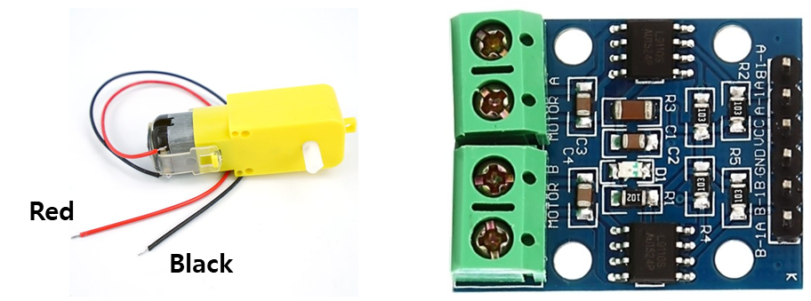
image

Connection Example

The following figure is an example of an input/output connection method of a motor driver(LS9110s).

  • Input

    • consists of a pair of 1A and 1B.

    • one for PWM, and the other for reference voltage.

      The reference voltage is Low or High.

  • Output

    • connect the input wires(Black and Red line) of DC motor, respectively.

    • the difference between the output values rotates the motor.

DC_motor_drive_case
DC_motor_drive_Config

As you can see, there are various combinations in the way wires are connected. So, you should control the motor properly according to connecting the wires.

The example was summarized thorough actual experiments. And it could not the correct answer for you. So, apply it according to your situation.

Troubleshooting

1. motor PWM duty ratio for different DIR

When, DIR=0 duty=0.8--> PWM 0.8 // // PWM delivered to the actual motor

Whe, DIR=1 duty=0.8--> PWM 0.2 // // PWM delivered to the actual motor

*** a solution ***

float targetPWM;  // pwm for motor input 
float duty=abs(DIR-targetPWM); // duty with consideration of DIR=1 or 0

PWM_duty(PWM_PIN, duty);

2. Motor does not run under duty 0.5

SOL) Configure motor PWM period as 1kHz

L298N Motor Driver (Channel A)

L298N pin map

Wiring

  • VS (“+12V”) → 5 V

  • Power GND ↔ Nucleo GND (common ground)

  • ENA ← PWM pin (e.g., PA0 / TIM2_CH1 (PA0))

  • IN1, IN2 ← two digital pins (DIR)

  • OUT1, OUT2 → motor leads (Use jumper/alligator leads.)

Operation

  • Speed: Controlled by PWM duty on ENA

  • Direction: Set by IN1/IN2

IN1
IN2
Motion

1

0

Forward

0

1

Reverse

Last updated

Was this helpful?