> For the complete documentation index, see [llms.txt](https://ykkim.gitbook.io/ec/llms.txt). Markdown versions of documentation pages are available by appending `.md` to page URLs; this page is available as [Markdown](https://ykkim.gitbook.io/ec/ec-course/tutorial/tutorial-7segment-display.md).
# Tutorial: 7-Segment Display
##
## Using 7-Segment Display in STM32F4
We will learn how to display a decimal number (0\~9) on a 7-segment display
* Inputs:
* Decimal number : 0\~9
* Binary: 4-bit numbers \[D C B A] // (0000\~ 1001)
* Output:
* 7-segment decoder: 7-bit numbers ( a to g)
* 7-segment display: decimal number 0\~9
####
We will learn how to configure the 7-segment display for different options
#### Option 1. With 7-segment decoder
#### Option 2. Without using 7-segment decoder
#### Option 3. Without using 7-segment decoder on JKIT evaluation board
####
## Circuit Description
### Hardware Specification
* 7-segment display: common anode (5101ASR)
* 7-segment decoder: [74LS47N (datasheet download)](https://pdf1.alldatasheet.com/datasheet-pdf/download/5724/MOTOROLA/SN74LS47N.html)
### 7-segment display (5101ASR)
For more detail information about 7 segment display - [click here](https://www.electronics-tutorials.ws/combination/comb_6.html)
* Common anode: (common pin is connected to VCC)
* Giving ‘LOW’ to the pin -> LED ON
* Needs a load resistor for each pin(led)
Check the difference between the common cathode and common anode.
> We will use common anode.

### BCD 7-segment decoder
Model: [74LS47N (datasheet download)](https://pdf1.alldatasheet.com/datasheet-pdf/download/5724/MOTOROLA/SN74LS47N.html)
* All output pins are active LOW
###
### Array resistor (B331J)

## Option 1. Connecting with a BCD 7-segment decoder
###
###
## Option 2. Connecting without a 7-segment decoder
### Circuit Configuration


### Example Code
Download the tutorial code
* `TU_GPIO_LED_7segment_student.c` [Click here for download](https://github.com/ykkimhgu/EC-student/tree/main/tutorial/tutorial-student)
* Program a function that works as a 7-segment decoder
```cpp
#include "stm32f4xx.h"
#include "ecRCC2.h"
#include "ecGPIO2.h"
void setup(void);
int main(void) {
// Initialiization --------------------------------------------------------
setup();
// Inifinite Loop ----------------------------------------------------------
while(1){
GPIO_write(PA_5, LOW);
GPIO_write(PA_6, LOW);
GPIO_write(PA_7, HIGH);
GPIO_write(PB_6, HIGH);
GPIO_write(PC_7, HIGH);
GPIO_write(PA_9, LOW);
GPIO_write(PA_8, LOW);
GPIO_write(PB_10, LOW);
}
}
void setup(void){
RCC_HSI_init();
GPIO_init(PA_5, OUTPUT);
GPIO_init(PA_6, OUTPUT);
GPIO_init(PA_7, OUTPUT);
GPIO_init(PB_6, OUTPUT);
GPIO_init(PC_7, OUTPUT);
GPIO_init(PA_9, OUTPUT);
GPIO_init(PA_8, OUTPUT);
GPIO_init(PB_10, OUTPUT);
}
```
## Option 3. Without using a 7-segment decoder on JKIT evaluation board
### Circuit Configuration
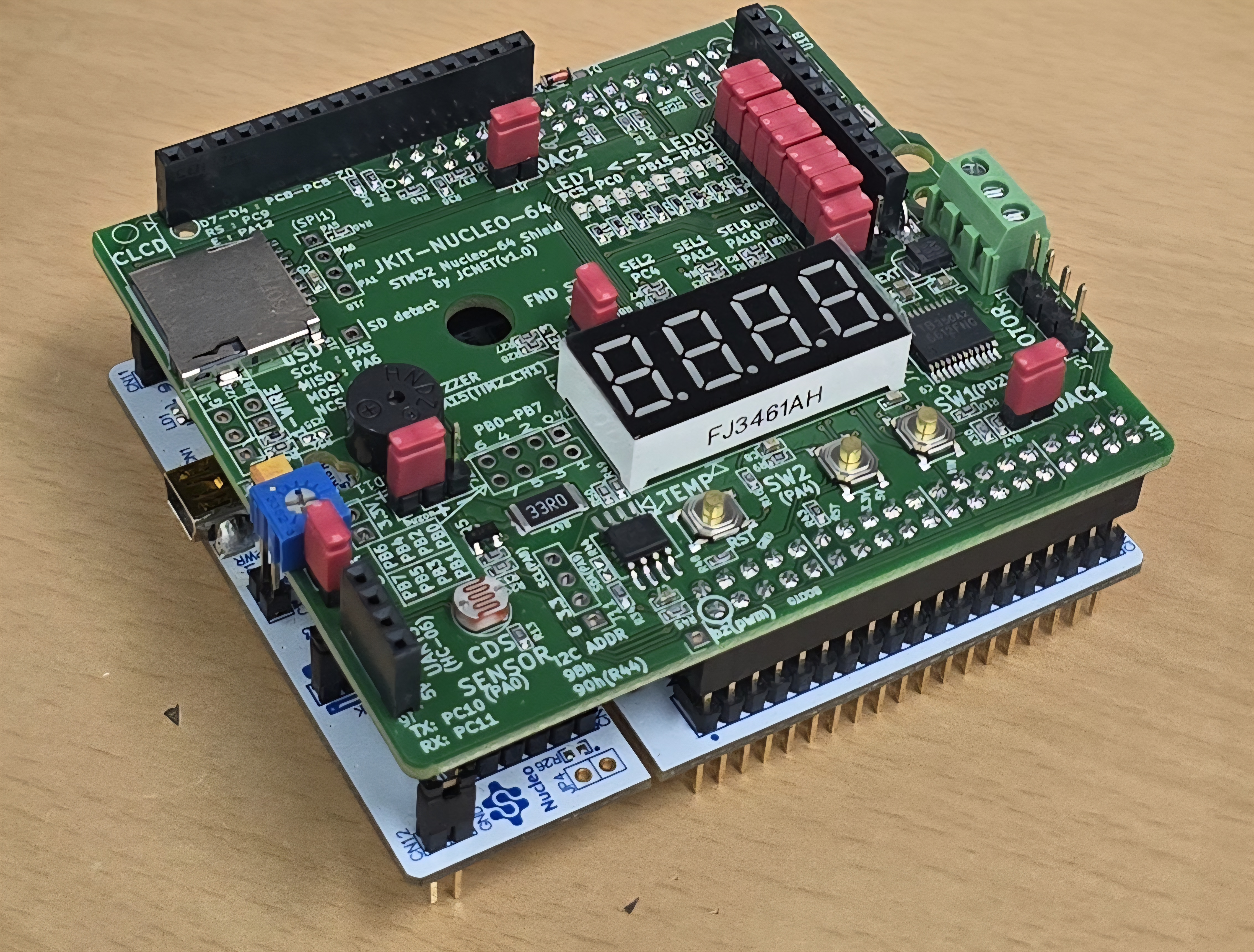
JKIT - Nucleo 64: [link](https://www.devicemart.co.kr/goods/view?no=14123215\&srsltid=AfmBOooT3zgaxGXZ_q0fvy4uZxHesTbwpqNprE6P3YXMk9V0EGoGrhLM)
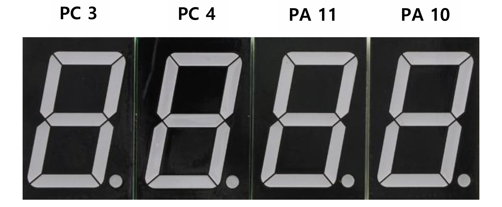
* There are four 7-Segment Displays. You need to choose which one to use.
* There is NO BCD decoder, you need to connect 7-segment display without using decoder.
{% hint style="info" %}
**7-segments display are Common Cathode: Giving 'High' to the pin -> LED on**
{% endhint %}
| 1. Digital Out: 7-Segment display number | 2. Digital Out: Select 7-Segment display |
| ------------------------------------------------------ | ---------------------------------------- |
| Digital Out | Digital Out |
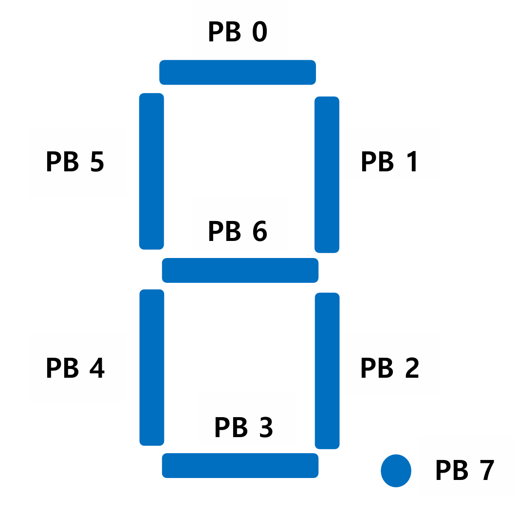
| PB\_7, PB\_6, PB\_5, PB\_4, PB\_3, PB\_2, PB\_1, PB\_0 | PC\_3, PC\_4, PA\_11, PA\_10 |
| Push-Pull | Push-Pull |
#### Example Code
```c
PinName_t led[8]={PB_7, PB_6, PB_5, PB_4, PB_3, PB_2, PB_1, PB_0};
//each led that has to light up gets a 1, every other led gets a 0
//its in order of the DigitalOut Pins above
int number[11][8]={
{1,1,1,0,1,1,1,0}, //zero
{0,0,1,0,0,1,0,0}, //one
{1,0,1,1,1,0,1,0}, //two
{1,0,1,1,0,1,1,0}, //three
{0,1,1,1,0,1,0,0}, //four
{1,1,0,1,0,1,1,0}, //five
{1,1,0,1,1,1,1,0}, //six
{1,0,1,0,0,1,0,0}, //seven
{1,1,1,1,1,1,1,0}, //eight
{1,1,1,1,0,1,1,0}, //nine
{0,0,0,0,0,0,0,1} //dot
};
//display shows the number in this case 6
int num=6;
for (int i=0; i<8; i++)
led[i] = number[num][i];
```
## Exercise
Create a simple code that can Select and Display a decimal number (0\~9) on 7-segment display (JKIT - Nucleo 64)
* Display Selection and Number
* (1) Selection of the display: 0\~3
* (2) Decimal Number to display: 0\~9
* Output Display:
* 7-segment displaying a decimal number: 0\~9
{% hint style="info" %}
If you want to display multiple 7-segment displays, you need to use a very short delay to display multiple numbers
{% endhint %}
**Exercise Code**
```c
#include "stm32f4xx.h"
#include "ecGPIO2.h"
#include "ecRCC2.h"
// Initialize 7 DOUT pins for 7 segment leds
void seven_seg_FND_init(void);
// Select display: 0 to 3
// Display a number 0 - 9 only
void seven_seg_FND_display(uint8_t num, uint8_t select);
void setup(void){
// Intialize System Clock
RCC_HSI_init();
// Intialize DOUT Pins
// and Others
// [YOUR CODE GOES HERE]
seven_seg_FND_init();
};
int main(void) {
setup();
uint8 numDisplay=8;
uint8 selectFND=0;
while (1) {
seven_seg_FND_display(numDisplay,selectFND);
}
}
// Initialize DOUT pins for 7 segment leds
void seven_seg_FND_init(void){
//pin name array
PinName_t pinsFND[12]={PB_7, PB_6, PB_5, PB_4, PB_3, PB_2, PB_1, PB_0, PC_3, PC_4, PA_11, PA_10};
//Iteratively initializing DOUT pins for pinsFND
// for (int i=0;i<8;i++)
// { initialize each pin as output};
// [YOUR CODE GOES HERE]
// [YOUR CODE GOES HERE]
}
// Select display: 0 to 3
// Display a number 0 - 9 only
void seven_seg_FND_display(uint8_t num, uint8_t select){
// [YOUR CODE GOES HERE]
// [YOUR CODE GOES HERE]
}
```