U(S)ART (Universal Asynchronous/synchronous Receiver and Transmitter)
We are going to create a simple program that links MCU-PC via UART communication. MCU can receive and transmit 8-bit character data through UART communication.
NUCLEO-F401RE board offers UART2 channel with USB connector.
Used for communication between the board and a computer or other devices.
Serial.begin(baudrate);// Initialize the serial port.Serial.available();// Get the number of bytes (characters) available for reading from the serial portSerial.read();// Reads incoming serial data.Serial.print(text);// Prints data to the serial port as human-readable ASCII text.
baudrate : the data rate in bits per second (9600, ...)
Create a new program named as ‘TU_arduino_UART’.
Write the following source code.
Example 1: Print the Input Key
char keyIn;voidsetup(){Serial.begin(9600);Serial.print("Hello Nucleo\r\n");}voidloop(){if(Serial.available()>0){ keyIn =Serial.read();if(keyIn =='\n')Serial.print("\r\n");elseif(keyIn)Serial.print(keyIn);}}
Choose ‘Serial’ tab -> Select ‘COMx: STMicroelectronics STLink’ port
COMx, x is the port number and it can be different for each connection.
teraterm
Open Serial port(시리얼 포트) in Setup(설정) tab, check if the baud rate is set as 9600 [bps].
teraterm2
Press the reset button(black) and verify the operation. If you put any letter in Tera Term, MCU will receive it and transmit it to PC immediately, so you can see the pushed letters showed in Tera Term.
Exercise
Object Proximity Detection
Print only when it detects the presence of an object.
Use your hand as the object and put it near the sensor
It should print " Warning! An object is too close"
Do not print anything when the object is not near.
The experiment kit has an IR proximal sensor that can detect the presence of an object.
We are going to create a simple program that measures the time to count 100 starting from 0. Print the result through UART communication.
Example: time measure
Create a new program named as ‘TU_arduino_Timer’.
Write the following source code.
Click on Upload button.
Open ‘Tera Term’ and make New Connection.
teraterm result
Push the reset button(black), and verify the time taken in counting 100.
You can measure time taken in any other processes like toggling LED, multiplication or division, etc. If the process takes long time, you can also measure time in [ms] unit using ‘millis()’ command.
Exercise
Time delay polling
Create a time delay function named as delaycnt(uint cnt)
It receives the number of counts that it should wait.
cnt should be from 0~ 255
Print how many micro-seconds it took during the waiting
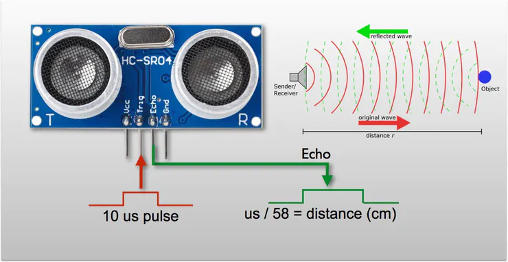
We are going to create a simple program that measure distance by using ultrasonic sensor ‘HC-SR04’ and print out result through UART communication.
Example: ultrasonic sensor distance
Create a new program named as ‘TU_mbed_PWM1’.
Write the following source code.
Click on Upload button.
Open ‘Tera Term’ and make New Connection.
Ultrasonic sensor ‘HC-SR04’ get trigger signal as 10[us] pwm through trig pin which generate on D10 pin. Also, you should capture the echo signal on D7 pin and measure its pulse-width to calculate the distance.
HC-SR04
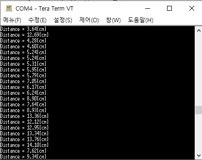
Press the reset button(black) and verify the operation. The distance between ultrasonic sensor and obstacle will be shown in Tera Term.
pwm3
Click on Upload button.
Press the reset button(black) and verify the operation. The distance between ultrasonic sensor and obstacle will be shown in Tera Term.
Exercise1:
Measure the distance (cm) and the pulse width (msec) and print both values.
What is the maximum and minimum distance it can measure
What is the accuracy of the distance you have measured with the ultrasonic sensor?
Show your experiment result and compare it with the exact distance measured by a ruler.
Exercise 2:
Generate a square pulse of 1~2Hz by using a function generator.
Measure the time period of the pulse in msec.
What is the accuracy when measuring the period? What can you do to improve the measurement accuracy?
PWM (Pulse Width Modulation) DC - Motor
We are going to create a simple program that run DC - Motor by giving pwm signal as input.
Create a new program named as ‘TU_arduino_PWM2’.
Write the following source code.
Click on Upload button.
Press the reset button(black) and verify the operation. If you press the user button, DC-Motor will turn on.
Exercise
Control Motor direction and speed with following configuration
As button B1 is pressed, increase PWM duty ratio by interval of 25%
0 - 0.25(CW) - 0.5(CW) - 0.75(CW) - 1(CW) - 0 - 0.25(CCW) - 0.5(CCW) and so on
Direction pin is PC_8 (But, you should wire PC8 to D9 and use D9 pin in arduino example.)
We are going to create a simple program that measures the output voltage of photo-resistor and print out the result through UART communication.
Exercise: analog photodetector
Create a new program named as ‘TU_arduino_AnalogIn.
Write the following source code.
Click on Upload button.
Open ‘Tera Term’ and make New Connection.
Photo-resistor module outputs low voltage under a bright condition, and vice versa.
ADC
Push the reset button(black) and verify the operation.
If you turn on the flashlight at the photo-resistor with your phone, the sensor output voltage will be decreased. When the output voltage is below 0.2V, which means high brightness is given, the LED(LD2) will be turned on.
Exercise 1: photodetection
Change different values for measure threshold to change the sensitivity of detection.
Under the brightness near the thresholding voltage, the led may flicker on and off. How can you change your code to avoid this flicker?
Exercise 2: sound sensor
The experiment kit has a sound sensor (microphone)[SZH-EK033]. You can change the sensitivity of the sound sensor by turning the variable resistor.
It is connected as AnalogInPinNameA5
SZH-EK033
For every second, print the value of the sound sensor
const int irSensorPin = 4;  // the number of IR sensor pin

int detectedState = HIGH;

void setup() {
  // Initialize the IR sensor pin as an input.
  // your code

  // Initialize the serial port.
  // your code
}

void loop() {
  // Read value from IR sensor
  // your code


  // print warning
  // your code
}
unsigned int cnt = 0;
unsigned long beginTime, endTime;

void setup() {
  // Initialize Serial port
  Serial.begin(9600);
  Serial.println(sizeof(unsigned int));
  Serial.print("Program START\r\n");
}

void loop() {
  cnt = 0;

  // call delaycnt() function
  // your code

  // Check how much time counting takes.
  Serial.printf("Counting %d takes %d [us]\r\n", cnt, endTime - beginTime);
  delay(500);
}

void delaycnt(unsigned int delayCnt){
  // check current time [us]
  // your code

  // counting until delayCnt value.
  // your code

  // check current time [us]
  // your code
}
const int pwmPin = 11;   // PWM pin
const int buttonPin = 3;  // button pin

int buttonState = HIGH;

void setup() {
  pinMode(pwmPin, OUTPUT);
  pinMode(buttonPin, INPUT);
}

void loop() {

  buttonState = digitalRead(buttonPin);

  if (buttonState == LOW){
    for (int i = 0; i < 10; i++){
      analogWrite(pwmPin, 40 + 10*i);
      delay(100);
    }

    for (int i = 10; i > 0; i--){
      analogWrite(pwmPin, 40 + 10*i);
      delay(100);
    }
  }
  else{
    analogWrite(pwmPin, 0);
  }
}
const int pwmPin = 11;   // PWM pin
const int buttonPin = 3;  // button pin

int buttonState = HIGH;

void setup() {
  pinMode(pwmPin, OUTPUT);

 // initialize the pushbutton pin as an input:
  pinMode(buttonPin, INPUT_PULLUP);
  attachInterrupt(digitalPinToInterrupt(buttonPin), motorOperation, CHANGE);
}

void loop() {

  if (buttonState == LOW){
    for (int i = 0; i < 10; i++){
      analogWrite(pwmPin, 40 + 10*i);
      delay(100);
    }

    for (int i = 10; i > 0; i--){
      analogWrite(pwmPin, 40 + 10*i);
      delay(100);
    }
  }
  else{
    analogWrite(pwmPin, 0);
  }
}

void motorOperation(){
  buttonState = digitalRead(buttonPin);
}
const int pwmPin = 11;  // PWM pin
const int btnPin = 3;   // button pin
const int dirPin = 9;   // direction pin

int cnt = 0;
int dir = LOW;

void setup() {
  // Initialize PWM pin as an output:
  // your code

  // Initialize the direction pin as an output:
  // your code

  // Initialize the push button pin as an interrupt input:
  // your code
}

void loop() {
  // Write the direction and speed command to each pins.
  // Hint: speed value can be expressed by 'cnt' variable.
  // speed value : 0 ~ 255
  // your code
}

void motorOperation(){
  // Use 'cnt' and 'dir' variables
  // your code
}
const int ledPin = 13;  // LED pin
const int soundPin = 5; // Sound sensor pin

float measure;          // the value measured from sound sensor.
int ledState = LOW;

void setup() {
  // Initialize the LED pin as an output.
  // your code

  // Initialize the serial port.
  // your code
}

void loop() {
  // the measured value needs to be transformed to voltage unit.
  // mapping(0 ~ 3.3V -> 0 ~ 1023)
  // [mV] (0 ~ 1023 -> 0 ~ 3300[mV])
  // your code

  // print measured value
  // your code

  // Change the LED state by measure threshold.
  // your code

  digitalWrite(ledPin, ledState);
  delay(200);
}