Date: 2025-09-26
Author/Partner:
Github: repository link
Demo Video: Youtube link
PDF version:
In this lab, you are required to create two simple programs using interrupt:
(1) displaying the number counting from 0 to 19 with Button Press
(2) counting at a rate of 1 second
You must submit
LAB Report (*.md & *.pdf)
Zip source files(main*.c, ecRCC2.h, ecGPIO2.h, ecSysTick2.c etc...).
Only the source files. Do not submit project files
PlatformIO, CMSIS, EC_HAL library
Tutorial: STM-Arduino
We are going to create a simple program that turns LED(LD2) on triggered by External Interrupt of user button(BT1)/
digitalPinToInterrupt(pin): translate the digital pin to the specific interrupt number.
ISR: a function called whenever the interrupt occurs.
mode: defines when the interrupt should be triggered. (LOW, CHANGE, RISING, FALLING)
Create a new project under the directory \EC\lab\LAB_EXTI
Open Arduino IDE and Create a new program named as ‘TU_arduino_EXTINT.ino ’.
Write the following code.
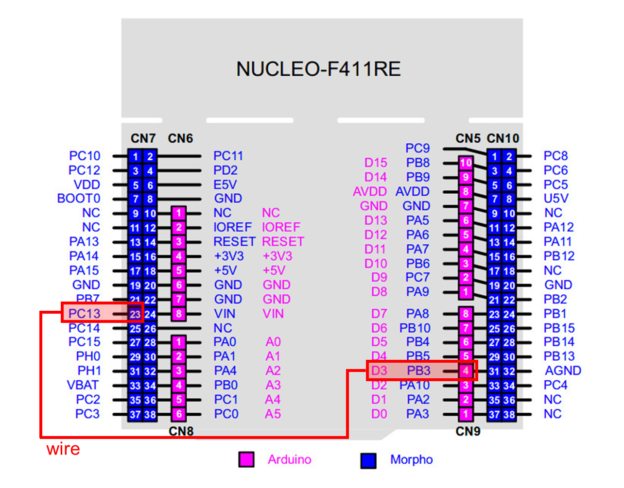
The user button pin is PC13, but this pin cannot be used in arduino. So, you should connect PC13 to pinName D3 by using wire.
Whenever the user button(BT1) is pressed (at fall), LED should be ON. When the button is released, the LED should be OFF.
Tutorial: STM32F4xx
1.Tutorial: Managing library header files
Read how to manage library header files for MCU register configurations. Apply it in your LAB.
2.Tutorial: Custom Initialization
Instead of writing initial setting functions for each registers, you can call a user defined function e.g. MCU_init() for the commonly used default initialization. Follow the tutorial and apply it in your LAB.
Creating EXTI library
Rename these files as ecEXTI2.h, ecEXTI2.c
You MUST write your name and other information at the top of the library code files.
Save these files in your directory EC \include\.
Declare and define the following functions in your library ecEXTI2.h
ecEXTI.h
Create a new project under the directory \EC\lab\LAB_EXTI
The project name is “LAB_EXTI”.
Create a new source file named as “LAB_EXTI.c”
You MUST write your name on the source file inside the comment section.
2. Include your updated library in \EC\include\ to your project.
First, check if every number, 0 to 9, can be displayed properly on each 7-segment (there are a total of 4 7-segment display on the evaluation board).
Then, create a code to display the number counting from 0 to 19 and repeating.
Count up only by pressing the push button
Must use External Interrupt
Digital In for Button (B1)
Digital Out for FND-7-Segment
PB7,PB6,PB5,PB4,PB3,PB2,PB1,PB0
('a''h', respectively)
PC3,PC4,PA11,PA10
('LED1' 'LED4', respectively)
Push-Pull, No PullUp-PullDown, Medium Speed
Circuit Diagram
You need to include the circuit diagram
We can use two different methods to detect an external signal: polling and interrupt. What are the advantages and disadvantages of each approach?
Answer discussion questions
What would happen if the EXTI interrupt handler does not clear the interrupt pending flag? Check with your code
Answer discussion questions
Your code goes here.
Explain your source code with the necessary comments.
Experiment images and results go here
Show experiment images /results
Add demo video linkarrow-up-right
Problem 2: Counting numbers on 7-Segment using SysTick
Display the number 0 to 9 on the 7-segment LED at the rate of 1 sec.
After displaying up to 9, then it should display ‘0’ and continue counting.
When the button is pressed, the number should be reset ‘0’ and start counting again.
SysTick Library
Rename these files as ecSysTick2.h, ecSysTick2.c
You MUST write your name and other information at the top of the library code files.
Save these files in your directory EC \include\.
Declare and define the following functions in your library : ecSysTick2.h
ecSysTick.h
Create a new project under the directory
\EC\lab\LAB_EXTI_SysTick
The project name is “LAB_EXTI_SysTick”.
Create a new source file named as “LAB_EXTI_SysTick.c”
You MUST write your name on the source file inside the comment section.
2. Include your updated library in \EC\include\ to your project.
ecSysTick2.h, ecSysTick2.c
First, check if every number, 0 to 9, can be displayed properly on the 7-segment.
Then, create a code to display the number counting from 0 to 9 and repeat at the rate of 1 second. (Use only one digit)
When the button is pressed, it should start from '0' again.
Use EXTI for this button reset.
Digital In for Button (B1)
Digital Out for FND-7-Segment
PB7,PB6,PB5,PB4,PB3,PB2,PB1,PB0
('a'~'h', respectively)
PA10
('LED4', respectively)
Push-Pull, No Pull-up-Pull-down, Medium Speed
Circuit Diagram
You need to include the circuit diagram
Your code goes here.
Explain your source code with necessary comments.
Experiment images and results
Show experiment images /results
Add demo video linkarrow-up-right
Complete list of all references used (github, blog, paper, etc)
Troubleshooting
(Option) You can write a Troubleshooting section
Last updated 3 months ago


