LAB: Input Capture - Ultrasonic
Date: 2024-10-10
Author/Partner:
Github: repository link
Demo Video: Youtube link
PDF version:
Introduction
In this lab, you are required to create a simple program that uses input capture mode to measure the distance using an ultrasonic distance sensor. The sensor also needs trigger pulses that can be generated by using the timer output.
You must submit
LAB Report (*.pdf & *.md)
Zip source files(main*.c, ecRCC.h, ecGPIO.h, ecSysTick.c etc...).
Only the source files. Do not submit project files
Requirement
Hardware
MCU
NUCLEO-F411RE
Actuator/Sensor/Others:
HC-SR04
breadboard
Software
Keil uVision, CMSIS, EC_HAL library
Tutorial: USART with Serial Monitor TeraTerm
Understand how to use serial monitor (TeraTerm) to display charicters(string) on PC sent from MCU.
Tutorial: STM-Arduino
We are going to create a simple program that measure distance by using ultrasonic sensor ‘HC-SR04’ and print out result through UART communication.
Procedure
Create a new project under the directory
\EC\LAB\TIMER_ICAPOpen Arduino IDE and Create a new program named as ‘TU_arduino_TIMER_ICAP.ino’.
Write the following code.
upload and run.
Click on Upload button.
Open ‘Tera Term’ and make New Connection.
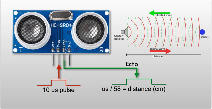
Ultrasonic sensor ‘HC-SR04’ get trigger signal as 10[us] pwm through trig pin which generate on D10 pin. Also, you should capture the echo signal on D7 pin and measure its pulse-width to calculate the distance.

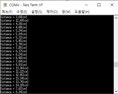
Press the reset button(black) and verify the operation. The distance between ultrasonic sensor and obstacle will be shown in Tera Term.

Click on Upload button.
Press the reset button(black) and verify the operation. The distance between ultrasonic sensor and obstacle will be shown in Tera Term.
Problem 1: Create HAL library
(Option 1) Use the provided library
Download Library Header Files (solution)
ecCAP2.h
(Option 2) Create your own library
Declare and Define the following functions in your library. You must update your header files located in the directory EC \lib\.
Download Library Header Files
Then, fill in the missing blanks
Problem 2: Ultrasonic Distance Sensor (HC-SR04)
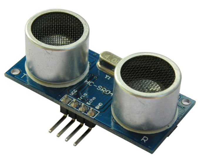
The HC-SR04 ultrasonic distance sensor. This economical sensor provides 2cm to 400cm of non-contact measurement functionality with a ranging accuracy that can reach up to 3mm. Each HC-SR04 module includes an ultrasonic transmitter, a receiver and a control circuit.

The HC-SR04 Ultrasonic Range Sensor Features:
Input Voltage: 5V
Current Draw: 20mA (Max)
Digital Output: 5V
Digital Output: 0V (Low)
Sensing Angle: 30° Cone
Angle of Effect: 15° Cone
Ultrasonic Frequency: 40kHz
Range: 2cm - 400cm
Procedure
1. Create a new project under the directory \repos\EC\LAB\LAB_TIMER_ICAP
The project name is “LAB_TIMER_ICAP”.
Create a new source file named as “LAB_TIMER_ICAP.c”
You MUST write your name on the source file inside the comment section.
2. Include your updated library in \repos\EC\lib\ to your project.
Now, your ecSTM32F4v2.h should be updated with
3. Connect the HC-SR04 ultrasonic distance sensor to MCU pins(PA6 - trigger, PB6 - echo), VCC and GND
Measurement of Distance
The program needs to
Generate a trigger pulse as PWM to the sensor.
Receive echo pulses from the ultrasonic sensor
Measure the distance by calculating pulse-width of the echo pulse.
Display measured distance in [cm] on serial monitor of Tera-Term for
(a) 10mm (b) 50mm (c) 100mm
Configuration
PLL (84MHz)
PA6 (TIM3_CH1)
PB6 (TIM4_CH1)
AF, Push-Pull, No Pull-up Pull-down, Fast
AF, No Pull-up Pull-down
PWM period: 50msec pulse width: 10usec
Counter Clock : 0.1MHz (10us) CH1 -> TI1 -> IC1 (rising edge) CH1 ->TI1 -> IC2 (falling edge)
Circuit Diagram
You need to include the circuit diagram

Discussion
There can be an over-capture case, when a new capture interrupt occurs before reading the CCR value. When does it occur and how can you calculate the time span accurately between two captures?
Answer discussion questions
In the tutorial, what is the accuracy when measuring the period of 1Hz square wave? Show your result.
Answer discussion questions
Code
Your code goes here: ADD Code LINK such as github
Explain your source code with necessary comments.
Example Code
Results
Experiment images and results
Show experiment images /results
Add demo video link
Reference
Complete list of all references used (github, blog, paper, etc)
Troubleshooting
(Option) You can write Troubleshooting section
Last updated