Debugging in uVision
Overview
Preparation
#include "stm32f4xx.h"
#define LED_PIN    5		//LD2
#define BUTTON_PIN 13


void RCC_HSI_init(void);   							//defined in ecRcc.h
void RCC_GPIOA_enable(void);
void RCC_GPIOC_enable(void);

int main(void) {
	/* Part 1. RCC GPIOA Register Setting */
		RCC_GPIOA_enable();
		RCC_GPIOC_enable();

	/* Part 2. GPIO Register Setting for OUTPUT*/
		// GPIO Mode Register
		GPIOA->MODER &= ~(3UL<<(2*LED_PIN)); // Clear '00' for Pin 5
		GPIOA->MODER |=   1UL<<(2*LED_PIN);  // Set '01' for Pin 5

		// GPIO Output Type Register
		GPIOA->OTYPER &= ~(1UL<<LED_PIN);   	// 0:Push-Pull

		// GPIO Pull-Up/Pull-Down Register
		GPIOA->PUPDR  &= ~(3UL<<(2*LED_PIN)); // 00: none

		// GPIO Output Speed Register
		GPIOA->OSPEEDR &= ~(3UL<<(2*LED_PIN));
		GPIOA->OSPEEDR |=   2UL<<(2*LED_PIN);  //10:Fast Speed


	/* Part 3. GPIO Register Setting for INPUT*/
		// GPIO Mode Register
		GPIOC->MODER &= ~(3UL<<(2*BUTTON_PIN)); // 00: Input

		// GPIO Pull-Up/Pull-Down Register
		GPIOC->PUPDR &= ~(3UL<<(2*BUTTON_PIN));
		GPIOC->PUPDR  |= 2UL<<(2*BUTTON_PIN); 	// 10: Pull-down


	/* Part 4. Deal loop  */
		while(1){
			unsigned int btVal=0;
			//Read bit value of Button
			btVal=(GPIOC->IDR) & (1UL << BUTTON_PIN);
			if(btVal == 0)
				GPIOA->ODR |= (1UL << LED_PIN);
			else
				GPIOA->ODR &= ~(1UL << LED_PIN);
		}
}


void RCC_GPIOA_enable()
{
		// HSI is used as system clock
		RCC_HSI_init();

		// RCC Peripheral Clock for GPIO_A Enable
		RCC->AHB1ENR |= RCC_AHB1ENR_GPIOAEN;
}

void RCC_GPIOC_enable()
{
		// HSI is used as system clock
		RCC_HSI_init();

		// RCC Peripheral Clock for GPIO_A Enable
		RCC->AHB1ENR |= RCC_AHB1ENR_GPIOCEN;
}


void RCC_HSI_init() {
	// Enable High Speed Internal Clock (HSI = 16 MHz)
  RCC->CR |= ((uint32_t)RCC_CR_HSION);

  // wait until HSI is ready
  while ( (RCC->CR & (uint32_t) RCC_CR_HSIRDY) == 0 ) {;}

  // Select HSI as system clock source
  RCC->CFGR &= (uint32_t)(~RCC_CFGR_SW);
  RCC->CFGR |= (uint32_t)RCC_CFGR_SW_HSI;

	// Wait till HSI is used as system clock source
  while ((RCC->CFGR & (uint32_t)RCC_CFGR_SWS) != 0 );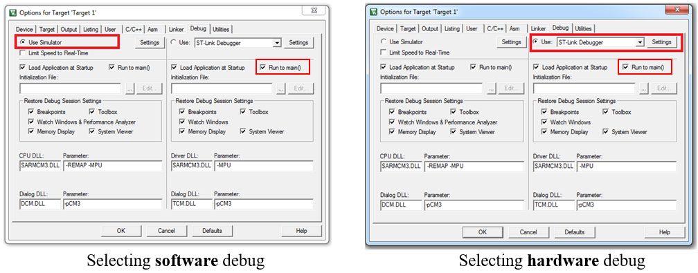
}Software vs Hardware Debug
Debug Control
Compile, Debug, and Run
You can program the STM32 flash by clicking the LOAD button
 .
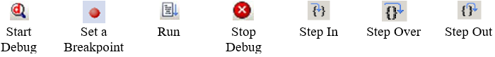
.Click the debug button
 to start the debug and click it again to exit the debug.
You can use the breakpoint button
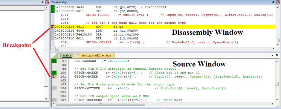
 to set a break point in either disassembly or source windows.
image
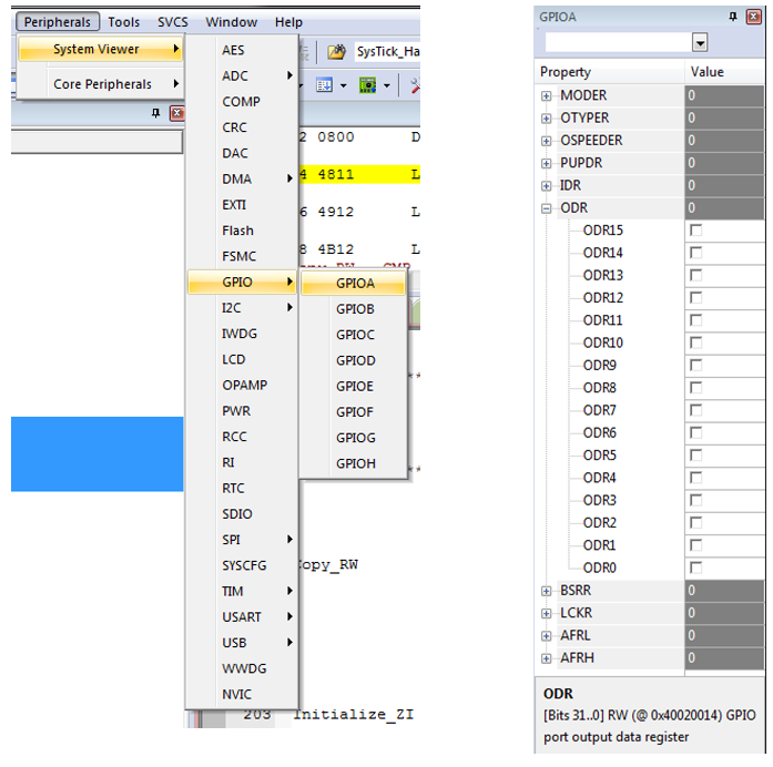
Pheripheral Registers
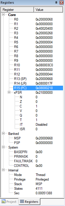
Processor Registers
Core Registers
xPSR
Description
Last updated