# LAB: Smart mini-fan with STM32-duino
## LAB: Smart mini-fan with STM32-duino
### I. Introduction
In this lab, you are required to create a simple program that uses arduino IDE for implementing a simple embedded digital application. Refer to online arduino references for the full list of APIs.
#### Hardware
NUCLEO -F401RE or NUCLEO -F411RE
Ultrasonic distance sensor(HC-SR04), DC motor (RK-280RA)
#### Software
Arduino IDE
### II. Procedure
The program needs to run the Fan only when the distance of an object is within a certain value.
Example: An automatic mini-fan that runs only when the face is near the fan. Otherwise turns off.
* As the button **B1** is pressed, change the fan velocity. The MODE(states) are
* MODE(state): **OFF(0%), MID(50%), HIGH(100%)**
* When the object(face) is detected about 50 mm away, then it automatically pauses the fan temporarily.
* Even the fan is temporarily paused, the MODE should be changed whenever the button **B1** is pressed
* When the object(face) is detected within 50mm, then it automatically runs the fan
* It must run at the speed of the current MODE
* LED(**LED1**): Turned OFF when MODE=OFF. Otherwise, blink the LED with 1 sec period (1s ON, 1s OFF)
* Print the distance and PWM duty ratio in Tera-Term console (every 1 sec).
* Must use Mealy FSM to control the mini-fan
* Draw a FSM(finite-state-machine) table and state diagram
* Example Table. See below for example codes

#### III. Configuration
**Ultrasonic distance sensor**
Trigger:
* Generate a trigger pulse as PWM to the sensor
* Pin: **D10** (TIM4 CH1)
* PWM out: 50ms period, 10us pulse-width
Echo:
* Receive echo pulses from the ultrasonic sensor
* Pin: **D7** (Timer1 CH1)
* Input Capture: Input mode
* Measure the distance by calculating pulse-width of the echo pulse.
**USART**
* Display measured distance in \[cm] on serial monitor of Tera-Term.
* Baudrate 9600
**DC Motor**
* PWM: PWM1, set 10ms of period by default
* Pin: **D11** (Timer1 CH1N)
### IV. Report & Score
You are required to write a concise lab report in 'md' format. On-Line submission.
**Lab Report:**
* Write Lab Title, Date, Your name
* Introduction
* Draw State Table and State Diagram to explain your logic \[30%]
* Explain your source code with necessary comments \[30%]
* External circuit diagram that connects MCU pins to peripherals(sensor/actuator) \[10%]
* Demonstration Video. Include the link in the report \[30%]
* Submit in both PDF and original file (\*.md etc)
## FSM Examples
### Example 1
**INPUT:**
* X: Button Pressed {0, 1}
**OUTPUT:**
* LED {ON, OFF}
**STATE:**
* S0: FAN OFF State
* S1: FAN ON State
#### Moore FSM Table
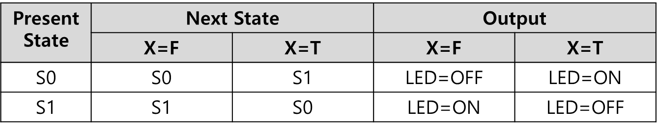
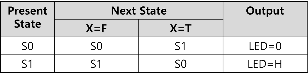 #### Mealy FSM Table
 #### Example Code
{% tabs %}
{% tab title="(C-prog) Moore Simple Example Code" %}
```cpp
#include
// State definition
#define S0 0
#define S1 1
#define LOW 0
#define HIGH 1
unsigned char state = S0;
unsigned char nextstate = S0;
unsigned char input = LOW;
unsigned char ledOut = LOW;
typedef struct {
unsigned int next[2]; // nextstate = FSM[state].next[input]
unsigned int out; // output = FSM[state].out
} State_t;
State_t FSM[2] = {
{{S0, S1},LOW},
{{S1, S0},HIGH}
};
int main()
{
printf("Start\n\r");
input=LOW;
nextstate = FSM[state].next[input];
state=nextstate;
ledOut = FSM[state].out;
printf("state=%d, ledOut=%d \n\r",state,ledOut);
input=HIGH;
nextstate = FSM[state].next[input];
state=nextstate;
ledOut = FSM[state].out;
printf("state=%d, ledOut=%d \n\r",state,ledOut);
input=LOW;
nextstate = FSM[state].next[input];
state=nextstate;
ledOut = FSM[state].out;
printf("state=%d, ledOut=%d \n\r",state,ledOut);
return 0;
}
```
{% endtab %}
{% tab title="(STMduino) Moore Example Code" %}
```cpp
// State definition
#define S0 0
#define S1 1
// Address number of output in array
#define LED 1
typedef struct {
uint32_t next[2]; // nextstate = FSM[state].next[input]
uint32_t out; // output = FSM[state].out
} State_t;
State_t FSM[2] = {
{{S0, S1},LOW},
{{S1, S0},HIGH}
};
const int ledPin = 13;
const int btnPin = 3;
unsigned char state = S0;
unsigned char input = 0;
unsigned char ledOut = LOW;
void setup() {
// initialize the LED pin as an output:
pinMode(ledPin, OUTPUT);
// initialize the pushbutton pin as an interrupt input:
pinMode(btnPin, INPUT_PULLUP);
attachInterrupt(digitalPinToInterrupt(btnPin), pressed, FALLING);
Serial.begin(9600);
}
void loop() {
// First, Update next state. Then, Output. Repeat
// 1. Update State <-- Next State
nextState();
// 2. Output of states - Logic
stateOutput();
digitalWrite(ledPin, ledOut);
delay(1000);
}
void pressed() {
input = 1;
}
void nextState() {
state = FSM[state].next[input];
// Intialize Button Pressed
input = 0;
}
void stateOutput() {
ledOut = FSM[state].out;
}
```
{% endtab %}
{% tab title="(C-prog) Mealy Simple Example Code" %}
```cpp
#include
// State definition
#define S0 0
#define S1 1
#define LOW 0
#define HIGH 1
unsigned char state = S0;
unsigned char nextstate = S0;
unsigned char input = LOW;
unsigned char ledOut = LOW;
// State table definition
typedef struct {
unsigned int next[2]; // nextstate = FSM[state].next[input]
unsigned int out[2]; // output = FSM[state].out[input]
} State_t;
State_t FSM[2] = {
{ {S0, S1},{LOW,HIGH} },
{ {S1, S0},{HIGH,LOW} }
};
int main()
{
printf("Start\n\r");
input=LOW;
ledOut = FSM[state].out[input];
nextstate = FSM[state].next[input];
state=nextstate;
printf("state=%d, ledOut=%d \n\r",state,ledOut);
input=HIGH;
ledOut = FSM[state].out[input];
nextstate = FSM[state].next[input];
state=nextstate;
printf("state=%d, ledOut=%d \n\r",state,ledOut);
input=LOW;
ledOut = FSM[state].out[input];
nextstate = FSM[state].next[input];
state=nextstate;
printf("state=%d, ledOut=%d \n\r",state,ledOut);
return 0;
}
```
{% endtab %}
{% tab title="(STMduino) Mealy Simple Example Code" %}
```cpp
// State definition
#define S0 0
#define S1 1
// Address number of output in array
#define PWM 0
#define LED 1
const int ledPin = 13;
const int pwmPin = 11;
const int btnPin = 3;
unsigned char state = S0;
unsigned char nextstate = S0;
unsigned char input = 0;
unsigned char ledOut = LOW;
unsigned char pwmOut = 0;
// State table definition
typedef struct {
unsigned int next[2]; // nextstate = FSM[state].next[input]
unsigned int out[2]; // output = FSM[state].out[input]
} State_t;
State_t FSM[2] = {
{ {S0, S1},{LOW,HIGH} },
{ {S1, S0},{HIGH,LOW} }
};
void setup() {
// initialize the LED pin as an output:
pinMode(ledPin, OUTPUT);
// initialize the pushbutton pin as an interrupt input:
pinMode(btnPin, INPUT_PULLUP);
attachInterrupt(digitalPinToInterrupt(btnPin), pressed, FALLING);
}
void loop() {
// First, Output of current State. Then Update next state. Repeat
// 1. Output State
stateOutput();
digitalWrite(ledPin, ledOut);
// 2. Update State <-- Next State
nextState();
delay(1000);
}
void pressed() {
input = 1;
}
void nextState() {
nextstate = FSM[state].next[input];
state = nextstate;
// Intialize Button Pressed
input = 0;
}
void stateOutput() {
ledOut = FSM[state].out[input];
}
```
{% endtab %}
{% endtabs %}
### Example 2
**INPUT:**
* X: Button Pressed {0, 1}
**OUTPUT:**
* VEL {0%, 100%}
* LED {ON, OFF}
**STATE:**
* S0: FAN OFF State
* S1: FAN ON State
#### Mealy FSM Table

#### Moore FSM Table

#### Example Code
{% tabs %}
{% tab title="Mealy Example Code" %}
```cpp
// State definition
#define S0 0
#define S1 1
const int ledPin = 13;
const int pwmPin = 11;
const int btnPin = 3;
unsigned char state = S0;
unsigned char nextstate = S0;
unsigned char input = 0;
unsigned char ledOut = LOW;
unsigned char pwmOut = 0;
void setup() {
// initialize the LED pin as an output:
pinMode(ledPin, OUTPUT);
// Initialize pwm pin as an output:
pinMode(pwmPin, OUTPUT);
// initialize the pushbutton pin as an interrupt input:
pinMode(btnPin, INPUT_PULLUP);
attachInterrupt(digitalPinToInterrupt(btnPin), pressed, FALLING);
}
void loop() {
// Calculate next state. then update State
nextState();
// Output
analogWrite(pwmPin, pwmOut);
digitalWrite(ledPin, ledOut);
delay(1000);
}
void pressed(){
input = 1;
}
void nextState(){
switch(state){
case S0:
if (input){
nextstate = S1;
pwmOut = 160;
ledOut = HIGH;
}
else{
nextstate = S0;
pwmOut = 0;
ledOut = LOW;
}
break;
case S1:
if (input){
nextstate = S0;
pwmOut = 0;
ledOut = LOW;
}
else {
nextstate = S1;
pwmOut = 160;
ledOut = HIGH;
}
break;
}
state = nextstate;
input = 0;
}
```
{% endtab %}
{% tab title="Mealy Example Code v2" %}
```cpp
// State definition
#define S0 0
#define S1 1
// Address number of output in array
#define PWM 0
#define LED 1
const int ledPin = 13;
const int pwmPin = 11;
const int btnPin = 3;
unsigned char state = S0;
unsigned char nextstate = S0;
unsigned char input = 0;
unsigned char ledOut = LOW;
unsigned char pwmOut = 0;
// State table definition
typedef struct {
uint32_t out[2][2]; // output = FSM[state].out[input][PWM or LED]
uint32_t next[2]; // nextstate = FSM[state].next[input]
} State_t;
State_t FSM[2] = {
{ {{0 , LOW }, {160, HIGH}}, {S0, S1} },
{ {{160, HIGH}, {0 , LOW }}, {S1, S0} }
};
void setup() {
// initialize the LED pin as an output:
pinMode(ledPin, OUTPUT);
// Initialize pwm pin as an output:
pinMode(pwmPin, OUTPUT);
// initialize the pushbutton pin as an interrupt input:
pinMode(btnPin, INPUT_PULLUP);
attachInterrupt(digitalPinToInterrupt(btnPin), pressed, FALLING);
}
void loop() {
// First, Output of current State. Then Update next state. Repeat
// 1. Output State
stateOutput();
analogWrite(pwmPin, pwmOut);
digitalWrite(ledPin, ledOut);
// 2. Update State <-- Next State
nextState();
delay(1000);
}
void pressed() {
input = 1;
}
void nextState() {
nextstate = FSM[state].next[input];
state = nextstate;
// Intialize Button Pressed
input = 0;
}
void stateOutput() {
pwmOut = FSM[state].out[input][PWM];
ledOut = FSM[state].out[input][LED];
}
```
{% endtab %}
{% tab title="Moore Example Code" %}
```cpp
// State definition
#define S0 0
#define S1 1
// Address number of output in array
#define PWM 0
#define LED 1
typedef struct {
uint32_t out[2]; // output = FSM[state].out[PWM or LED]
uint32_t next[2]; // nextstate = FSM[state].next[input]
} State_t;
State_t FSM[2] = {
{{0 , LOW }, {S0, S1}},
{{160 , HIGH}, {S1, S0}}
};
const int ledPin = 13;
const int pwmPin = 11;
const int btnPin = 3;
unsigned char state = S0;
unsigned char input = 0;
unsigned char pwmOut = 0;
unsigned char ledOut = LOW;
void setup() {
// initialize the LED pin as an output:
pinMode(ledPin, OUTPUT);
// Initialize pwm pin as an output:
pinMode(pwmPin, OUTPUT);
// initialize the pushbutton pin as an interrupt input:
pinMode(btnPin, INPUT_PULLUP);
attachInterrupt(digitalPinToInterrupt(btnPin), pressed, FALLING);
Serial.begin(9600);
}
void loop() {
// First, Update next state. Then, Output. Repeat
// 1. Update State <-- Next State
nextState();
// 2. Output of states
stateOutput();
analogWrite(pwmPin, pwmOut);
digitalWrite(ledPin, ledOut);
delay(1000);
}
void pressed() {
input = 1;
}
void nextState() {
state = FSM[state].next[input];
// Intialize Button Pressed
input = 0;
}
void stateOutput() {
pwmOut = FSM[state].out[PWM];
ledOut = FSM[state].out[LED];
}
```
{% endtab %}
{% endtabs %}
### FSM Example 3
**INPUT:**
* X: Button Pressed {0, 1}
* Y: Object Detected {0, 1}
**OUTPUT:**
* VEL {0%, 50% 100%}
* LED {ON, OFF}
**STATE:**
* S0: FAN OFF State
* S1: FAN MID State
* S2: FAN HIGH State
* P\_50: FAN 50% PAUSE State
* P\_100: FAN 100% PAUSE State
#### Mealy FSM Table
EXERCISE

#### Moore FSM Table

#### Example Code
{% tabs %}
{% tab title="\[EXERCISE] Mealy Code" %}
```cpp
// State definition
#define S0 0
#define S1 1
#define S2 2
const int ledPin = 13;
const int pwmPin = 11;
const int btnPin = 3;
int state = S0;
int bPressed = 0;
int ledOn = LOW;
void setup() {
// [TO-DO] YOUR CODE GOES HERE
}
void loop() {
// [TO-DO] YOUR CODE GOES HERE
// Output State
stateOutput();
// [TO-DO] YOUR CODE GOES HERE
// Calculate next state, then update State
nextState();
// [TO-DO] YOUR CODE GOES HERE
}
void pressed(){
bPressed = 1;
}
void nextState(){
// [TO-DO] YOUR CODE GOES HERE
// Output
analogWrite(pwmPin, pwm);
digitalWrite(ledPin, ledState);
}
void stateOutput(){
// [TO-DO] YOUR CODE GOES HERE
}
```
{% endtab %}
{% tab title="Moore Example Code" %}
```cpp
// State definition
#define S0 0 // Fan OFF
#define S1 1 // Fan vel = 50%
#define S2 2 // Fan vel = 100%
#define P50 3 // Pause (vel = 50%)
#define P100 4 // Pause (vel = 100%)
// Address number of output in array
#define PWM 0
#define LED 1
// State table definition
typedef struct {
uint32_t out[2]; // output = FSM[state].out[PWM or LED]
uint32_t next[2][2]; // nextstate = FSM[state].next[input X][input Y]
} State_t;
State_t FSM[5] = {
{ {0 , LOW }, {{S0 , S0}, {P50 , S1}} },
{ {80 , HIGH}, {{P50 , S1}, {P100, S2}} },
{ {160 , HIGH}, {{P100, S2}, {S0 , S0}} },
{ {0 , HIGH}, {{P50 , S1}, {P100, S2}} },
{ {0 , HIGH}, {{P100, S2}, {S0 , S0}} },
};
// Pin setting
const int ledPin = 13;
const int pwmPin = 11;
const int btnPin = 3;
const int trigPin = 10;
const int echoPin = 7;
unsigned char state = S0;
unsigned char input[2] = {0, 0};
unsigned char pwmOut = 0;
unsigned char ledOut = LOW;
unsigned long duration;
float distance;
int thresh = 5;
void setup() {
// initialize the LED pin as an output:
pinMode(ledPin, OUTPUT);
// Initialize pwm pin as an output:
pinMode(pwmPin, OUTPUT);
// initialize the pushbutton pin as an interrupt input:
pinMode(btnPin, INPUT_PULLUP);
attachInterrupt(digitalPinToInterrupt(btnPin), pressed, FALLING);
// Initialize the trigger pin as an output
pinMode(trigPin, OUTPUT);
// Initialize the echo pin as an input
pinMode(echoPin, INPUT);
Serial.begin(9600);
}
void loop() {
// Generate pwm singal on the trigger pin.
digitalWrite(trigPin, LOW);
delayMicroseconds(2);
digitalWrite(trigPin, HIGH);
delayMicroseconds(10);
digitalWrite(trigPin, LOW);
delayMicroseconds(10);
// Distance is calculated using how much time it takes.
duration = pulseIn(echoPin, HIGH);
distance = (float)duration / 58.0;
// Calculate next state. then update State
nextState();
// Output of states
stateOutput();
analogWrite(pwmPin, pwmOut);
digitalWrite(ledPin, ledOut);
Serial.print("distance = ");
Serial.print(distance);
Serial.println(" [cm]");
delay(1000);
}
void pressed(){
input[0] = 1;
nextState();
input[0] = 0;
}
void nextState(){
if (distance < thresh)
input[1] = 1;
else
input[1] = 0;
// get nextState
state = FSM[state].next[input[0]][input[1]];
}
void stateOutput(){
pwmOut = FSM[state].out[PWM];
ledOut = FSM[state].out[LED];
}
```
{% endtab %}
{% endtabs %}
#### Example Code
{% tabs %}
{% tab title="(C-prog) Moore Simple Example Code" %}
```cpp
#include
// State definition
#define S0 0
#define S1 1
#define LOW 0
#define HIGH 1
unsigned char state = S0;
unsigned char nextstate = S0;
unsigned char input = LOW;
unsigned char ledOut = LOW;
typedef struct {
unsigned int next[2]; // nextstate = FSM[state].next[input]
unsigned int out; // output = FSM[state].out
} State_t;
State_t FSM[2] = {
{{S0, S1},LOW},
{{S1, S0},HIGH}
};
int main()
{
printf("Start\n\r");
input=LOW;
nextstate = FSM[state].next[input];
state=nextstate;
ledOut = FSM[state].out;
printf("state=%d, ledOut=%d \n\r",state,ledOut);
input=HIGH;
nextstate = FSM[state].next[input];
state=nextstate;
ledOut = FSM[state].out;
printf("state=%d, ledOut=%d \n\r",state,ledOut);
input=LOW;
nextstate = FSM[state].next[input];
state=nextstate;
ledOut = FSM[state].out;
printf("state=%d, ledOut=%d \n\r",state,ledOut);
return 0;
}
```
{% endtab %}
{% tab title="(STMduino) Moore Example Code" %}
```cpp
// State definition
#define S0 0
#define S1 1
// Address number of output in array
#define LED 1
typedef struct {
uint32_t next[2]; // nextstate = FSM[state].next[input]
uint32_t out; // output = FSM[state].out
} State_t;
State_t FSM[2] = {
{{S0, S1},LOW},
{{S1, S0},HIGH}
};
const int ledPin = 13;
const int btnPin = 3;
unsigned char state = S0;
unsigned char input = 0;
unsigned char ledOut = LOW;
void setup() {
// initialize the LED pin as an output:
pinMode(ledPin, OUTPUT);
// initialize the pushbutton pin as an interrupt input:
pinMode(btnPin, INPUT_PULLUP);
attachInterrupt(digitalPinToInterrupt(btnPin), pressed, FALLING);
Serial.begin(9600);
}
void loop() {
// First, Update next state. Then, Output. Repeat
// 1. Update State <-- Next State
nextState();
// 2. Output of states - Logic
stateOutput();
digitalWrite(ledPin, ledOut);
delay(1000);
}
void pressed() {
input = 1;
}
void nextState() {
state = FSM[state].next[input];
// Intialize Button Pressed
input = 0;
}
void stateOutput() {
ledOut = FSM[state].out;
}
```
{% endtab %}
{% tab title="(C-prog) Mealy Simple Example Code" %}
```cpp
#include
// State definition
#define S0 0
#define S1 1
#define LOW 0
#define HIGH 1
unsigned char state = S0;
unsigned char nextstate = S0;
unsigned char input = LOW;
unsigned char ledOut = LOW;
// State table definition
typedef struct {
unsigned int next[2]; // nextstate = FSM[state].next[input]
unsigned int out[2]; // output = FSM[state].out[input]
} State_t;
State_t FSM[2] = {
{ {S0, S1},{LOW,HIGH} },
{ {S1, S0},{HIGH,LOW} }
};
int main()
{
printf("Start\n\r");
input=LOW;
ledOut = FSM[state].out[input];
nextstate = FSM[state].next[input];
state=nextstate;
printf("state=%d, ledOut=%d \n\r",state,ledOut);
input=HIGH;
ledOut = FSM[state].out[input];
nextstate = FSM[state].next[input];
state=nextstate;
printf("state=%d, ledOut=%d \n\r",state,ledOut);
input=LOW;
ledOut = FSM[state].out[input];
nextstate = FSM[state].next[input];
state=nextstate;
printf("state=%d, ledOut=%d \n\r",state,ledOut);
return 0;
}
```
{% endtab %}
{% tab title="(STMduino) Mealy Simple Example Code" %}
```cpp
// State definition
#define S0 0
#define S1 1
// Address number of output in array
#define PWM 0
#define LED 1
const int ledPin = 13;
const int pwmPin = 11;
const int btnPin = 3;
unsigned char state = S0;
unsigned char nextstate = S0;
unsigned char input = 0;
unsigned char ledOut = LOW;
unsigned char pwmOut = 0;
// State table definition
typedef struct {
unsigned int next[2]; // nextstate = FSM[state].next[input]
unsigned int out[2]; // output = FSM[state].out[input]
} State_t;
State_t FSM[2] = {
{ {S0, S1},{LOW,HIGH} },
{ {S1, S0},{HIGH,LOW} }
};
void setup() {
// initialize the LED pin as an output:
pinMode(ledPin, OUTPUT);
// initialize the pushbutton pin as an interrupt input:
pinMode(btnPin, INPUT_PULLUP);
attachInterrupt(digitalPinToInterrupt(btnPin), pressed, FALLING);
}
void loop() {
// First, Output of current State. Then Update next state. Repeat
// 1. Output State
stateOutput();
digitalWrite(ledPin, ledOut);
// 2. Update State <-- Next State
nextState();
delay(1000);
}
void pressed() {
input = 1;
}
void nextState() {
nextstate = FSM[state].next[input];
state = nextstate;
// Intialize Button Pressed
input = 0;
}
void stateOutput() {
ledOut = FSM[state].out[input];
}
```
{% endtab %}
{% endtabs %}
### Example 2
**INPUT:**
* X: Button Pressed {0, 1}
**OUTPUT:**
* VEL {0%, 100%}
* LED {ON, OFF}
**STATE:**
* S0: FAN OFF State
* S1: FAN ON State
#### Mealy FSM Table

#### Moore FSM Table

#### Example Code
{% tabs %}
{% tab title="Mealy Example Code" %}
```cpp
// State definition
#define S0 0
#define S1 1
const int ledPin = 13;
const int pwmPin = 11;
const int btnPin = 3;
unsigned char state = S0;
unsigned char nextstate = S0;
unsigned char input = 0;
unsigned char ledOut = LOW;
unsigned char pwmOut = 0;
void setup() {
// initialize the LED pin as an output:
pinMode(ledPin, OUTPUT);
// Initialize pwm pin as an output:
pinMode(pwmPin, OUTPUT);
// initialize the pushbutton pin as an interrupt input:
pinMode(btnPin, INPUT_PULLUP);
attachInterrupt(digitalPinToInterrupt(btnPin), pressed, FALLING);
}
void loop() {
// Calculate next state. then update State
nextState();
// Output
analogWrite(pwmPin, pwmOut);
digitalWrite(ledPin, ledOut);
delay(1000);
}
void pressed(){
input = 1;
}
void nextState(){
switch(state){
case S0:
if (input){
nextstate = S1;
pwmOut = 160;
ledOut = HIGH;
}
else{
nextstate = S0;
pwmOut = 0;
ledOut = LOW;
}
break;
case S1:
if (input){
nextstate = S0;
pwmOut = 0;
ledOut = LOW;
}
else {
nextstate = S1;
pwmOut = 160;
ledOut = HIGH;
}
break;
}
state = nextstate;
input = 0;
}
```
{% endtab %}
{% tab title="Mealy Example Code v2" %}
```cpp
// State definition
#define S0 0
#define S1 1
// Address number of output in array
#define PWM 0
#define LED 1
const int ledPin = 13;
const int pwmPin = 11;
const int btnPin = 3;
unsigned char state = S0;
unsigned char nextstate = S0;
unsigned char input = 0;
unsigned char ledOut = LOW;
unsigned char pwmOut = 0;
// State table definition
typedef struct {
uint32_t out[2][2]; // output = FSM[state].out[input][PWM or LED]
uint32_t next[2]; // nextstate = FSM[state].next[input]
} State_t;
State_t FSM[2] = {
{ {{0 , LOW }, {160, HIGH}}, {S0, S1} },
{ {{160, HIGH}, {0 , LOW }}, {S1, S0} }
};
void setup() {
// initialize the LED pin as an output:
pinMode(ledPin, OUTPUT);
// Initialize pwm pin as an output:
pinMode(pwmPin, OUTPUT);
// initialize the pushbutton pin as an interrupt input:
pinMode(btnPin, INPUT_PULLUP);
attachInterrupt(digitalPinToInterrupt(btnPin), pressed, FALLING);
}
void loop() {
// First, Output of current State. Then Update next state. Repeat
// 1. Output State
stateOutput();
analogWrite(pwmPin, pwmOut);
digitalWrite(ledPin, ledOut);
// 2. Update State <-- Next State
nextState();
delay(1000);
}
void pressed() {
input = 1;
}
void nextState() {
nextstate = FSM[state].next[input];
state = nextstate;
// Intialize Button Pressed
input = 0;
}
void stateOutput() {
pwmOut = FSM[state].out[input][PWM];
ledOut = FSM[state].out[input][LED];
}
```
{% endtab %}
{% tab title="Moore Example Code" %}
```cpp
// State definition
#define S0 0
#define S1 1
// Address number of output in array
#define PWM 0
#define LED 1
typedef struct {
uint32_t out[2]; // output = FSM[state].out[PWM or LED]
uint32_t next[2]; // nextstate = FSM[state].next[input]
} State_t;
State_t FSM[2] = {
{{0 , LOW }, {S0, S1}},
{{160 , HIGH}, {S1, S0}}
};
const int ledPin = 13;
const int pwmPin = 11;
const int btnPin = 3;
unsigned char state = S0;
unsigned char input = 0;
unsigned char pwmOut = 0;
unsigned char ledOut = LOW;
void setup() {
// initialize the LED pin as an output:
pinMode(ledPin, OUTPUT);
// Initialize pwm pin as an output:
pinMode(pwmPin, OUTPUT);
// initialize the pushbutton pin as an interrupt input:
pinMode(btnPin, INPUT_PULLUP);
attachInterrupt(digitalPinToInterrupt(btnPin), pressed, FALLING);
Serial.begin(9600);
}
void loop() {
// First, Update next state. Then, Output. Repeat
// 1. Update State <-- Next State
nextState();
// 2. Output of states
stateOutput();
analogWrite(pwmPin, pwmOut);
digitalWrite(ledPin, ledOut);
delay(1000);
}
void pressed() {
input = 1;
}
void nextState() {
state = FSM[state].next[input];
// Intialize Button Pressed
input = 0;
}
void stateOutput() {
pwmOut = FSM[state].out[PWM];
ledOut = FSM[state].out[LED];
}
```
{% endtab %}
{% endtabs %}
### FSM Example 3
**INPUT:**
* X: Button Pressed {0, 1}
* Y: Object Detected {0, 1}
**OUTPUT:**
* VEL {0%, 50% 100%}
* LED {ON, OFF}
**STATE:**
* S0: FAN OFF State
* S1: FAN MID State
* S2: FAN HIGH State
* P\_50: FAN 50% PAUSE State
* P\_100: FAN 100% PAUSE State
#### Mealy FSM Table
EXERCISE

#### Moore FSM Table

#### Example Code
{% tabs %}
{% tab title="\[EXERCISE] Mealy Code" %}
```cpp
// State definition
#define S0 0
#define S1 1
#define S2 2
const int ledPin = 13;
const int pwmPin = 11;
const int btnPin = 3;
int state = S0;
int bPressed = 0;
int ledOn = LOW;
void setup() {
// [TO-DO] YOUR CODE GOES HERE
}
void loop() {
// [TO-DO] YOUR CODE GOES HERE
// Output State
stateOutput();
// [TO-DO] YOUR CODE GOES HERE
// Calculate next state, then update State
nextState();
// [TO-DO] YOUR CODE GOES HERE
}
void pressed(){
bPressed = 1;
}
void nextState(){
// [TO-DO] YOUR CODE GOES HERE
// Output
analogWrite(pwmPin, pwm);
digitalWrite(ledPin, ledState);
}
void stateOutput(){
// [TO-DO] YOUR CODE GOES HERE
}
```
{% endtab %}
{% tab title="Moore Example Code" %}
```cpp
// State definition
#define S0 0 // Fan OFF
#define S1 1 // Fan vel = 50%
#define S2 2 // Fan vel = 100%
#define P50 3 // Pause (vel = 50%)
#define P100 4 // Pause (vel = 100%)
// Address number of output in array
#define PWM 0
#define LED 1
// State table definition
typedef struct {
uint32_t out[2]; // output = FSM[state].out[PWM or LED]
uint32_t next[2][2]; // nextstate = FSM[state].next[input X][input Y]
} State_t;
State_t FSM[5] = {
{ {0 , LOW }, {{S0 , S0}, {P50 , S1}} },
{ {80 , HIGH}, {{P50 , S1}, {P100, S2}} },
{ {160 , HIGH}, {{P100, S2}, {S0 , S0}} },
{ {0 , HIGH}, {{P50 , S1}, {P100, S2}} },
{ {0 , HIGH}, {{P100, S2}, {S0 , S0}} },
};
// Pin setting
const int ledPin = 13;
const int pwmPin = 11;
const int btnPin = 3;
const int trigPin = 10;
const int echoPin = 7;
unsigned char state = S0;
unsigned char input[2] = {0, 0};
unsigned char pwmOut = 0;
unsigned char ledOut = LOW;
unsigned long duration;
float distance;
int thresh = 5;
void setup() {
// initialize the LED pin as an output:
pinMode(ledPin, OUTPUT);
// Initialize pwm pin as an output:
pinMode(pwmPin, OUTPUT);
// initialize the pushbutton pin as an interrupt input:
pinMode(btnPin, INPUT_PULLUP);
attachInterrupt(digitalPinToInterrupt(btnPin), pressed, FALLING);
// Initialize the trigger pin as an output
pinMode(trigPin, OUTPUT);
// Initialize the echo pin as an input
pinMode(echoPin, INPUT);
Serial.begin(9600);
}
void loop() {
// Generate pwm singal on the trigger pin.
digitalWrite(trigPin, LOW);
delayMicroseconds(2);
digitalWrite(trigPin, HIGH);
delayMicroseconds(10);
digitalWrite(trigPin, LOW);
delayMicroseconds(10);
// Distance is calculated using how much time it takes.
duration = pulseIn(echoPin, HIGH);
distance = (float)duration / 58.0;
// Calculate next state. then update State
nextState();
// Output of states
stateOutput();
analogWrite(pwmPin, pwmOut);
digitalWrite(ledPin, ledOut);
Serial.print("distance = ");
Serial.print(distance);
Serial.println(" [cm]");
delay(1000);
}
void pressed(){
input[0] = 1;
nextState();
input[0] = 0;
}
void nextState(){
if (distance < thresh)
input[1] = 1;
else
input[1] = 0;
// get nextState
state = FSM[state].next[input[0]][input[1]];
}
void stateOutput(){
pwmOut = FSM[state].out[PWM];
ledOut = FSM[state].out[LED];
}
```
{% endtab %}
{% endtabs %}