LAB: Stepper Motor
Date: 2023-09-26
Author/Partner:
Github: repository link
Demo Video: Youtube link
PDF version:
Introduction
In this lab, we will learn how to drive a stepper motor with digital output of GPIOs of MCU. You will use a FSM to design the algorithm for stepper motor control.
You must submit
LAB Report (*.pdf & *.md)
Zip source files(main*.c, ecRCC.h, ecGPIO.h, ecSysTick.c etc...).
Only the source files. Do not submit project files
Requirement
Hardware
MCU
NUCLEO-F411RE
Actuator/Sensor/Others:
3Stepper Motor 28BYJ-48
Motor Driver A4988 (tutorial)
Motor Driver ULN2003 (lab)
breadboard
Software
Keil uVision, CMSIS, EC_HAL library
Tutorial: STM-Arduino
We are going to create a simple program that runs a stepper motor using A4988 motor driver See here for A4988 spec sheet
Here, you only need to give pulses to the driver. You can also change the microstepping setup.
Procedure
Connect the motor driver and the stepper motor as follows.
Supply 5~8 [V] to the driver using a power supply.
Create a new project under the directory
\EC\LAB\STEPPEROpen Arduino IDE and Create a new program named as ‘TU_arduino_Stepper.ino’.
Write the following code.
upload and run.
Press the reset button(black) and verify the operation.
Tutorial: FSM
You have to program the stepping sequence using the state table. You can define the states using structures.
Read Tutorial: FSM programming for hints
Tutorial: Finite State Machine programmingProblem : Stepper Motor with 4-input sequence
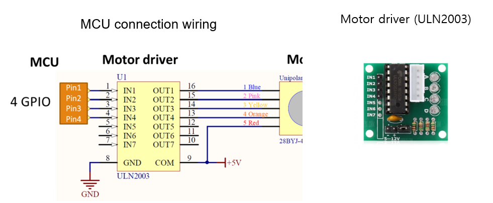
For the lab, we are going to use another stepper motor driver of ULN2003 motor driver.
See here for ULN2003 spec sheet
Here, you have to give 4-input pulses in sequence.
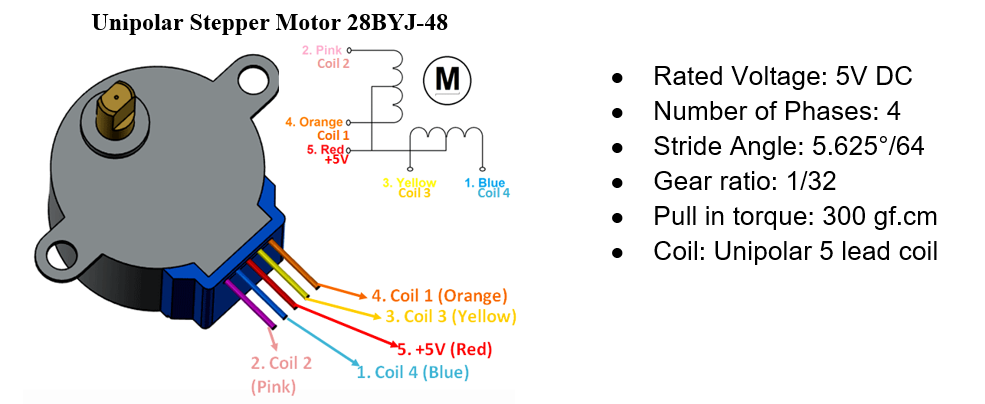
Hardware Connection
Read the specification sheet of the motor and the motor driver for wiring and min/max input voltage/current.
Stepper Motor Sequence
We will use unipolar stepper motor for this lab
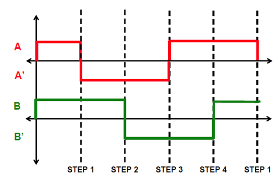
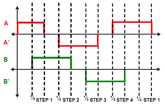
Fill in the blanks of each output data depending on the below sequence.
Full-stepping sequence

Half-stepping sequence

Finite State Machine
Draw a State Table for Full-Step Sequence. You can choose either Moore FSM or Mealy.
Full-Stepping Sequence

Half-Stepping Sequence
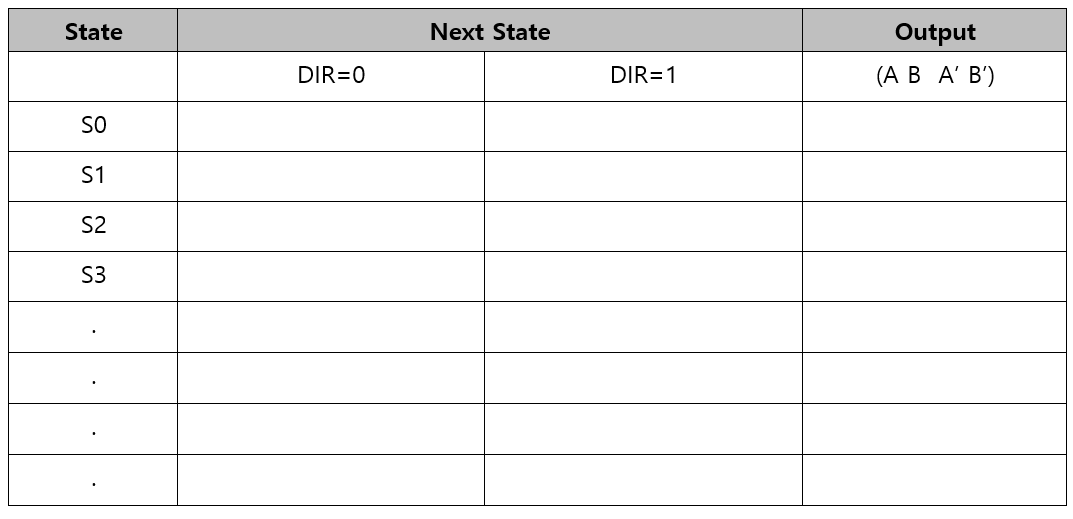
You have to program the stepping sequence using the state table. You can define the states using structures.
Example Code: Output Pins = A-B-A'-B'
Create HAL library
Download files:
Then, change the library files as ecStepper.h, ecStepper.c
Declare and define the following functions in your library.
You must update your header files located in the directory EC \lib\.
ecStepper.h
Note that these are blocking stepper controllers.
While the stepper is running, the MCU cannot process other polling commands. If you can, modify it to be the non-blocking controller.
You can also create your own functions different from the given instructions.
Procedure
Create a new project under the directory
\repos\EC\LAB\LAB_Stepper_MotorThe project name is “LAB_Stepper_Motor”.
Create a new source file named as “LAB_Stepper_Motor.c”
You MUST write your name on the source file inside the comment section.
Include your updated library in
\repos\EC\lib\to your project.ecGPIO.h, ecGPIO.c
ecRCC.h, ecRCC.c
ecEXTI.h, ecEXTI.c
ecSysTick.h, ecSysTick.c
ecStepper.h ecStepper.h
Connect the MCU to the motor driver and the stepper motor.
Find out the number of steps required to rotate 1 revolution using Full-steppping.
Then, rotate the stepper motor 10 revolutions with 2 rpm. Measure if the motor rotates one revolution per second.
Repeat the above process in the opposite direction.
Increase and decrease the speed of the motor as fast as it can rotate to find the maximum and minimum speed of the motor.
Apply the half-stepping and repeat the above.
Configuration
PB10, PB4, PB5, PB3 NO Pull-up Pull-down Push-Pull Fast
delay()
Discussion
Find out the trapezoid-shape velocity profile for a stepper motor. When is this profile necessary?
Answer discussion questions
How would you change the code more efficiently for micro-stepping control? You don’t have to code this but need to explain your strategy.
Answer discussion questions
There are other types of Stepper Motor Drivers that are simple to use, such as you only give one pulse signal and direction, instead of giving 4 pulse signals. Such examples are A4988, DRV 8834, and TB6600 drivers. Compare these motor drivers with ULN2003 in terms of operating method.
Answer discussion questions
Code
Your code goes here: ADD Code LINK such as github
Explain your source code with necessary comments.
Sample Code : Stepper Motor
Results
Experiment images and results
Show experiment images /results
Add demo video link
Reference
Complete list of all references used (github, blog, paper, etc)
Troubleshooting
(Option) You can write Troubleshooting section
Last updated