LAB: USART - Bluetooth
Date: 2025-09-26
Author/Partner:
Github: repository link
Demo Video: Youtube link
PDF version:
Introduction
In this lab, we will learn how to configure and use ‘USART(Universal synchronous asynchronous receiver transmitter)’ of MCU. Then, we will learn how to communicate between your PC and MCU and MCU to another MCU with wired serial communication.
Mission 1: Control LED(LD2) of each other MCU.
Mission 2: Run DC motors with Bluetooth

You must submit
LAB Report (*.md & *.pdf)
Zip source files(main*.c, ecRCC.h, ecGPIO.h, ecSysTick.c etc...).
Only the source files. Do not submit project files
Requirement
Hardware
MCU
NUCLEO-F411RE
Actuator/Sensor/Others:
DC motor, DC motor driver(L9110s),
Bluetooth Module(HC-06),
Software
Keil uVision, CMSIS, EC_HAL library
Preparation
Install the serial monitor: TeraTerm
Tutorial: USART with TeraTermProblem 1: EC HAL library
Using library
Option 1: Use the given library
Download the following files:
ecUART2.c
ecUART2.h
Option 2: Create your own library
Download the following files and fill in the empty spaces in the code.:
ecUART2_exercise_student.c
ecUART2_exercise_student.h
Then, change their names as
ecUART2.c
ecUART2.h
You must update your header files located in the directory EC\include\.
ecUSART2.h
Problem 2: Communicate MCU1-MCU2 using RS-232

Procedure
1. Create a new project under the directory \repos\EC\LAB\LAB_USART_LED
The project name is “LAB_USART_LED”.
Create a new source files named as “LAB_USART_LED.c”
You MUST write your name on the source file inside the comment section.
2. Include your updated library in \repos\EC\include\ or \repos\EC\lib\ to your project.
ecUART2.h, ecUART2.c
Update ecSTM32F4v2.h
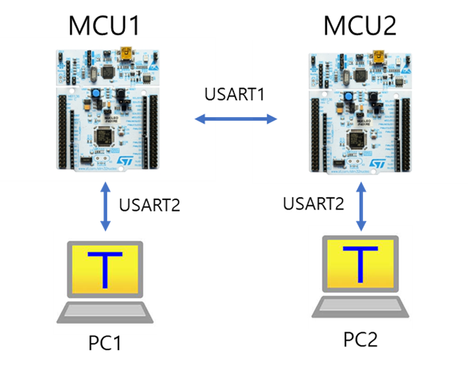
3. Connect each MCUs to each PC with USART 2 via USB cable (ST-Link)
MCU1 to PC1
MCU2 to PC2
4. Connect MCU1 to MCU2 with USART 1
connect RX/TX pins externally with jumper wires as
MCU1_TX to MCU2_RXD
MCU1_RX to MCU2_TX
Connect GND pins between MCU1-MCU2
MUST connect the same GND pin for MCU1 and MCU2
Send a message from PC_1 by typing keys on Teraterm. It should send that message from MCU_1 to MCU_2.
Note that you have to press "Enter" to end the message.
The received message by MCU_2 should be displayed on PC_2.
Turn other MCU's LED(LD2) On/OFF by sending text:
Press key "L" for Turn OFF LED
Press key "H" for Turn ON LED
Configuration
System Clock
PLL 84MHz
USART2 : USB cable (ST-Link)
No Parity, 8-bit Data, 1-bit Stop bit, 38400 baud-rate
USART1 : MCU1 - MCU2
TXD: PA9 RXD: PA10
No Parity, 8-bit Data, 1-bit Stop bit, 38400 baud-rate
Digital Out: LD2
PA5
Example Code
Example codes for communicating between two USARTs
Example 1 : RX/TX one character at a time
Receive (Interrupt), Send (Polling)
Display my key input on PC monitor (myKeyboard-->USART2 --> Serial monitor)
Display the received message on PC monitor(USART1--> USART2 --> Serial monitor)
Example 2 : RX/TX a string
Code
Your code goes here: ADD Code LINK such as github
Explain your source code with necessary comments.
Result
Experiment images and results
Show experiment images /results
Add demo video link
Problem 3: Control DC Motor via Bluetooth

Tutorial: Bluetooth
Follow the tutorial for Bluetooth setting.
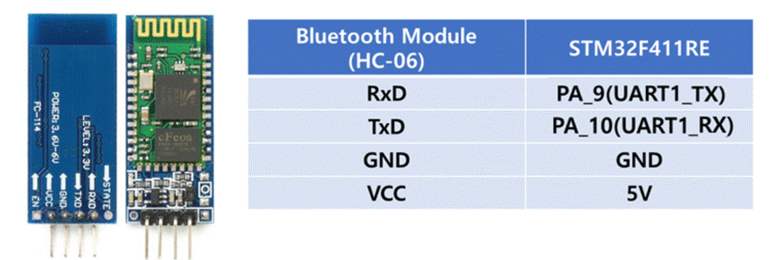
Tutorial: BluetoothSearch for the bluetooth module specification sheet (HC-06) and study the pin configurations.
The default PIN number is 1234.
Example of connecting to USART1

Procedure
1. Create a new project under the directory `\repos\EC\LAB\LAB_USART_Bluetooth
The project name is “LAB_USART_Bluetooth”.
Create a new source files named as “LAB_USART_Bluetooth.c”
You MUST write your name on the source file inside the comment section.
2. Include your updated library in \repos\EC\include\ or \repos\EC\lib\ to your project.
ecUART2.h, ecUART2.c
Update ecSTM32F4v2.h
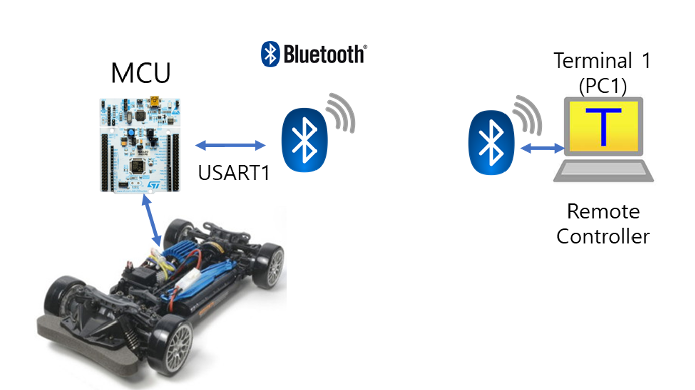
3. Connect the MCU - BT module. Use USART 1
Connect RX/TX pins as
MCU TX - BT RX
MCU RX - BT TX
4. Connect the BT module (HC-06) in PC's bluetooth setting.
Check the Bluetooth connection by turning MCU's LED(LD2) ON/OFF by sending text of "0" or "1" from PC.
Connect 2 x DC motors to MCU/Motor Driver
Control motor by the Keyboard inputs
Press 'J' : To turn Left
MotorA / MotorB = (50 / 80%) duty
Press 'L' : Turn Right
MotorA / MotorB = (80 / 50%) duty
Press 'I' : Go straight
MotorA / MotorB = (80 / 80 %) duty
Press 'K' : STOP
MotorA / MotorB = (0 / 0 %) duty
You may use other the key inputs as your preference.
Configuration
System Clock
PLL 84MHz
USART1 : MCU -Bluetooth
TXD: PA9 RXD: PA10
No Parity, 8-bit Data, 1-bit Stop bit, 9600 baud-rate
Digital Out: LD2
PA5
PWM (Motor A)
TIM2-Ch1
PWM period (2kHz~10kHz)
PWM (Motor B)
TIM2-Ch2
Code
Your code goes here: ADD Code LINK such as github
Explain your source code with necessary comments.
Result
Experiment images and results
Show experiment images /results
Add demo video link
Reference
Complete list of all references used (github, blog, paper, etc)
Troubleshooting
1. Cannot find my bluetooth module in my PC
Change your BT searching setting in your Window
Last updated