U(S)ART (Universal Asynchronous/synchronous Receiver and Transmitter)
We are going to create a simple program that links MCU-PC via UART communication. MCU can receive and transmit 8-bit character data through UART communication.
NUCLEO-F401RE board offers UART2 channel with USB connector.
/* * Copyright (c) 2020 Arm Limited and affiliates. * SPDX-License-Identifier: Apache-2.0*/#include "mbed.h"// Maximum number of element the application buffer can contain#define MAXIMUM_BUFFER_SIZE 32// Create a DigitalOutput object to toggle an LED whenever data is received.staticDigitalOutled(LED1);// Create a BufferedSerial object with a default baud rate.staticBufferedSerialserial_port(USBTX,USBRX);intmain(void){// Set desired properties (9600-8-N-1).serial_port.set_baud(9600);serial_port.set_format(/* bits */8,/* parity */BufferedSerial::None,/* stop bit */1);// Application buffer to receive the datacharbuf[MAXIMUM_BUFFER_SIZE]={0};while(1){if(uint32_t num =serial_port.read(buf,sizeof(buf))){// Toggle the LED. led =!led;// Echo the input back to the terminal.serial_port.write(buf, num);}}}
Example 2: Printing every 3 seconds
Click on Compile button. Then, the binary files will be created and downloaded. Copy the binary file to MCU board via USB cable.
Choose ‘Serial’ tab -> Select ‘COMx: STMicroelectronics STLink’ port
COMx, x is the port number and it can be different for each connection.
teraterm
Open Serial port(시리얼 포트) in Setup(설정) tab, check if the baud rate is set as 9600 [bps].
teraterm2
Press the reset button(black) and verify the operation. If you put any letter in Tera Term, MCU will receive it and transmit it to PC immediately, so you can see the pushed letters showed in Tera Term.
Exercise
The experiment kit has an IR proximal sensor that can detect the presence of an object.
It is connected at PinName D4 DigitalIn
IR proximity sensor (NS-IRPSM)
Print only when it detects the presence of object by placing your hand near the sensor.
" Warning! An object is too close"
Do not print anything when the object is not near.
Timer
We are going to create a simple program that measures the time to count 100 starting from 0. Print the result through UART communication.
Look up in mbed documentation for the fulll list of methods
Create a **** new program named as ‘TU_mbed_Timer’.
Write the following source code on ‘main.cpp’
Click on Compile button. Then, the binary files will be created and downloaded. Copy the binary file to MCU board via USB cable.
Open ‘Tera Term’ and make New Connection.
teraterm result
Push the reset button(black), and verify the time taken in counting 100. You can measure time taken in any other processes like toggling LED, multiplication or division, etc. If the process takes long time, you can also measure time in [ms] unit using ‘timer.read_ms()’ command.
PWM (Pulse Width Modulation) Ultra Sonic Sensor
We are going to create a simple program that measure distance by using ultrasonic sensor ‘HC-SR04’ and print out result through UART communication.
Look up in mbed documentation for the fulll list of methods
Create a **** new program named as ‘TU_mbed_PWM1’.
Write the following source code on ‘main.cpp’
Click on Compile button. Then, the binary files will be created and downloaded. Copy the binary file to MCU board via USB cable.
Open ‘Tera Term’ and make New Connection.
Ultrasonic sensor ‘HC-SR04’ get trigger signal as 10[us] pwm through trig pin which generate on D10 pin. Also, you should capture the echo signal on D7 pin and measure its pulse-width to calculate the distance.
HC-SR04
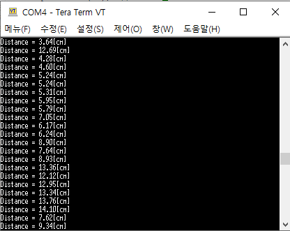
Press the reset button(black) and verify the operation. The distance between ultrasonic sensor and obstacle will be shown in Tera Term.
pwm3
Click on Compile button. Then, the binary files will be created and downloaded. Copy the binary file to MCU board via USB cable.
Press the reset button(black) and verify the operation. The distance between ultrasonic sensor and obstacle will be shown in Tera Term.
Exercise_1:
Measure the distance (cm) and the pulse width (msec) and print both values.
What is the maximum and minimum distance it can measure
What is the accuracy of the distance you have measured with the ultrasonic sensor?
Show your experiment result and compare it with the exact distance measured by a ruler.
Exercise_2:
Generate a square pulse of 1~2Hz by using a function generator.
Measure the time period of the pulse in msec.
What is the accuracy when measuring the period? What can you do to improve the measurement accuracy?
PWM (Pulse Width Modulation) DC - Motor
We are going to create a simple program that run DC - Motor by giving pwm signal as input.
Create a **** new program named as ‘TU_mbed_PWM2’.
Write the following source code on ‘main.cpp’
Click on Compile button. Then, the binary files will be created and downloaded. Copy the binary file to MCU board via USB cable.
Press the reset button(black) and verify the operation. If you press the user button, DC-Motor will turn on.
Exercise
Control Motor direction and speed with following configuration
Direction pin is PC_8: PinName PC_8
DIR=1, CW
DIR=0, CCW
PWM period is 1msec
As button B1 is pressed, increase PWM duty ratio by interval of 25%
0 - 0.25(CW)- 0.5(CW)-0.75(CW)-1(CW)- 0 - 0.25(CCW)- 0.5(CCW) and so on
ADC
We are going to create a simple program that measures the output voltage of photo-resistor and print out the result through UART communication.
Look up in mbed documentation for the fulll list of methods
Create a **** new program named as ‘TU_mbed_AnalogIn.
Write the following source code on ‘main.cpp’
Click on Compile button. Then, the binary files will be created and downloaded. Copy the binary file to MCU board via USB cable.
Open ‘Tera Term’ and make New Connection.
Photo-resistor module outputs low voltage under a bright condition, and vice versa.
ADC
Push the reset button(black) and verify the operation. If you turn on the flashlight at the photo-resistor with your phone, the sensor output voltage will be decreased. When the output voltage is below 0.2V, which means high brightness is given, the LED(LD2) will be turned on.
Exercise_1
Change different values for measure threshold to change the sensitivity of detection.
Under the brightness near the thresholding voltage, the led may flicker on and off. How can you change your code to avoid this flicker?
Exercise_2
The experiment kit has a sound sensor (microphone)[SZH-EK033]. You can change the sensitivity of the sound sensor by turning the variable resistor.
It is connected as AnalogInPinName A5
For every second, print the value of the sound sensor
Check the max value the sensor can print.
Turn LED on/off by clapping your hand.
Bluetooth
We are going to create a simple program that links MCU-PC via Bluetooth communication. MCU can receive and transmit 8-bit character data through the Bluetooth communication.
The experiment kit has Bluetooth HC-05.
You can connect the MCU to PC via bluetooth or an APP.
#include "mbed.h"

void printStatus(void);
void ledToggle(void);


Serial  uart(USBTX, USBRX, 9600);
Ticker  printTick;
Ticker  ledTick;
DigitalOut led(LED1);
unsigned int bPrint=0;


int main()
{
    uart.printf("Program START \t");

    led=1;
    ledTick.attach(&ledToggle,1);

    printTick.attach(&printStatus,3);

    while (true) {
        if (bPrint)
        {
            uart.printf("LED is %d\t", led.read());
            bPrint=0;
        }
        wait(0.1);
    }
}


void printStatus(void)
{
    bPrint=1;
}

void ledToggle(void)
{
    led=!led;
}
#include "mbed.h"

Timer       timer;
Serial      pc(USBTX, USBRX, 9600); // for using ‘printf()’

int beginTime, endTime;
int cnt = 0;

int main(void){
    pc.printf("Program START\t");
    while(1){
        cnt =0;
        timer.start();

        beginTime = timer.read_us();

        wait(0.3);
        endTime = timer.read_us();
        timer.stop();

        pc.printf("Counting %d takes %d [us]\n", cnt, endTime-beginTime);
        wait(0.5);
    }
}
#include "mbed.h"

Timer       timer;
Serial      pc(USBTX, USBRX, 9600); // for using ‘printf()’

int begin, end;
int cnt = 0;

int main(void){

    timer.start();

    begin = timer.read_us();

    while(cnt < 100) cnt++;

    end = timer.read_us();

    pc.printf("Counting 100 takes %d [us]\n", end-begin);

    wait(0.5);
}
#include "mbed.h"

Serial      pc(USBTX, USBRX, 9600);
PwmOut      trig(D10); // Trigger 핀
InterruptIn echo(D7);  // Echo 핀
Timer       tim;

int begin = 0;
int end = 0;

void rising(){
    begin = tim.read_us();
}

void falling(){
    end = tim.read_us();
}

int main(void){
    float distance = 0;

    trig.period_ms(60);     // period      = 60ms
    trig.pulsewidth_us(10); // pulse-width = 10us

    echo.rise(&rising);
    echo.fall(&falling);

    tim.start();

    while(1){
        distance =  (float)(end - begin) / 58; // [cm]
        pc.printf("Distance = %.2f[cm]\r\n", distance);
        wait(0.5);
    }
}
#include "mbed.h"

PwmOut pwm1(D11);
DigitalIn  button(USER_BUTTON);

int flag = 0;

int main() {
    pwm1.period_ms(10);
    while(1){
        if(!button) flag = 1;
        else flag = 0;
        if (flag == 1){
            for(int i=0; i<10; i++){
                pwm1.pulsewidth_ms(i);
                wait(0.1);
                }
            for(int i=0; i<10; i++){
                pwm1.pulsewidth_ms(10- i);
                wait(0.1);
                }
            }
        else {
                pwm1.pulsewidth_ms(0);
        }
    }
}