💾
EC
  • Introduction
  • EC Course
    • Syllabus
    • Preparation for EC
    • Tutorial
      • Tutorial: arduino-stm32
        • Tutorial: arduino-stm32 Installation
        • Tutorial: arduino-stm32 Part1
        • Tutorial: arduino-stm32 Part2
      • Tutorial: MDK uVision
        • Tutorial: Installing MDK uVision
        • Tutorial: Create a Project with uVision
        • Tutorial: Adding library header in uVision
        • Tutorial: Re-using Project Configuration
        • Debugging in uVision
      • Tutorial: PlatformIO in CLion
      • Tutorial: PlatformIO in VSCode
      • Tutorial: Repository Management
      • Tutorial: Managing library header files
      • Tutorial: PinName Configuration
      • Tutorial: Bitwise Macro
      • Tutorial: Custom initialization
      • Tutorial: Documentation
      • Tutorial: Creating Application API
      • Tutorial: 7-Segment Display
      • Tutorial: DC motor driver connection
      • Tutorial: USART with TeraTerm
      • Tutorial: Finite State Machine programming
      • Tutorial: Bluetooth
      • Tutorial: Zigbee with Nucleo board
    • LAB
      • LAB Report Template
      • LAB: Smart mini-fan with STM32-duino
      • LAB: Portable Fan with mbed
      • LAB: GPIO Digital InOut
      • LAB: GPIO Digital InOut 7-segment
      • LAB: EXTI & SysTick
      • LAB: Timer & PWM
      • LAB: Stepper Motor
      • LAB: Input Capture - Ultrasonic
      • LAB: USART - LED, Bluetooth
      • LAB: ADC - IR reflective sensor
      • LAB: Line Tracing RC Car
    • Sample code
      • Code Templates
    • Hardware
      • Nucleo-F411RE
      • LAB Hardware
        • Electronic Chips
        • HUINS Embedded Kit
    • Projects
      • Line Tracing Car Project
      • Design Project
        • Past Projects
      • Project Grading Criteria
    • Study Resource for MCU
      • Hexa-Decimal Table
      • Bitwise Op for Register
      • System Clock
      • Timer
      • USART
      • ADC
  • STM32 M4 Programming
    • Documentation
      • C++ API Docs
    • Firmware Library
      • PinName Configuration
      • GPIO Digital
      • RCC
      • EXTI_SysTick
      • TIMER
      • USART
    • Troubleshooting
    • mbed for STM32
      • Tutorial: mbed-Part 1
      • Tutorial: mbed - Part 2
      • Tutorial: mbed - Part 3
      • Using mbed API on uVision
    • mbed OS
  • Other Programming
    • Arduino
    • Socket Programming
      • Window Socket Programming
      • Arduino WiFi
    • Cube-MX
    • Github
    • Markdown
      • Example: API documentation
    • MATLAB
  • C Programming
    • C-Programming Lessons
      • Installing Visual Studio Community
        • Visual Studio Community 2022
      • Installing VS Code(Mac/Linux)
      • Creating Header Lib
      • Pointer
      • Array
      • 2D Array
      • Structure
      • Dynamic Alloc
      • Bitwise Operation
  • Numerical Programming
    • Syllabus
    • Preparation for NP
    • Math Review
    • Tutorial
      • TA Session Video
      • Tutorial: NP Library Header Files
      • Tutorial - Sine Taylor
      • Tutorial: Passing a Function, Function callback
      • Tutorial: Nonlinear solver
      • Tutorial: Differentiation
      • Tutorial: Integration
      • Tutorial: Matrix Structure
      • Tutorial: Eigenvalue problem
      • Tutorial: ODE-IVP
      • Tutorial: Curve Fitting
      • Tutorial: Create Github Repos of NP lib
      • Tutorial: Version Control in Github
      • Tutorial: Documentation with Markdown
      • Exercise: Version Control and Documentation
    • Example: MATLAB
    • Example: NP Library
    • Assignment
      • Assignment Factorial and Power
      • Assignment: Version Control and Documentation
    • Problem Bank
Powered by GitBook
On this page
  • Introduction
  • Requirement
  • Tutorial: STM-Arduino
  • Procedure
  • Tutorial: STM32F4xx
  • 1.Tutorial: Managing library header files
  • 2.Tutorial: Custom Initialization
  • Problem 1: Counting numbers on 7-Segment using EXTI Button
  • 1-1. Create HAL library
  • 1-2. Procedure
  • Configuration
  • Circuit Diagram
  • Discussion
  • Code
  • Results
  • Problem 2: Counting numbers on 7-Segment using SysTick
  • 2-1. Create HAL library
  • 2-2. Procedure
  • Configuration
  • Circuit Diagram
  • Code
  • Results
  • Reference
  • Troubleshooting

Was this helpful?

  1. EC Course
  2. LAB

LAB: EXTI & SysTick

Date: 2023-09-26

Author/Partner:

Github: repository link

Demo Video: Youtube link

PDF version:

Introduction

In this lab, you are required to create two simple programs using interrupt:

(1) displaying the number counting from 0 to 9 with Button Press

(2) counting at a rate of 1 second

You must submit

  • LAB Report (*.md & *.pdf)

  • Zip source files(main*.c, ecRCC2.h, ecGPIO2.h, ecSysTick2.c etc...).

    • Only the source files. Do not submit project files

Requirement

Hardware

  • MCU

    • NUCLEO-F411RE

  • Actuator/Sensor/Others:

    • 4 LEDs and load resistance

    • 7-segment display(5101ASR)

    • Array resistor (330 ohm)

    • breadboard

Software

  • Keil uVision, CMSIS, EC_HAL library

Tutorial: STM-Arduino

We are going to create a simple program that turns LED(LD2) on triggered by External Interrupt of user button(BT1)/

attachInterrupt(digitalPinToInterrupt(pin), ISR, mode)
  • digitalPinToInterrupt(pin): translate the digital pin to the specific interrupt number.

  • ISR: a function called whenever the interrupt occurs.

  • mode: defines when the interrupt should be triggered. (LOW, CHANGE, RISING, FALLING)

Procedure

  1. Create a new project under the directory \EC\LAB\LAB_EXTI

  2. Open Arduino IDE and Create a new program named as ‘TU_arduino_EXTINT.ino’.

  3. Write the following code.

const int btnPin = 3;
const int ledPin =  13; 

int btnState = HIGH;

void setup() {
    pinMode(ledPin, OUTPUT);
    pinMode(btnPin, INPUT_PULLUP);
    attachInterrupt(digitalPinToInterrupt(btnPin), blink, CHANGE);
}

void loop() {
    // blank
}


void blink(){
    btnState = digitalRead(btnPin);

    if (btnState == HIGH)
        digitalWrite(ledPin, LOW);
    else 
        digitalWrite(ledPin, HIGH);
}

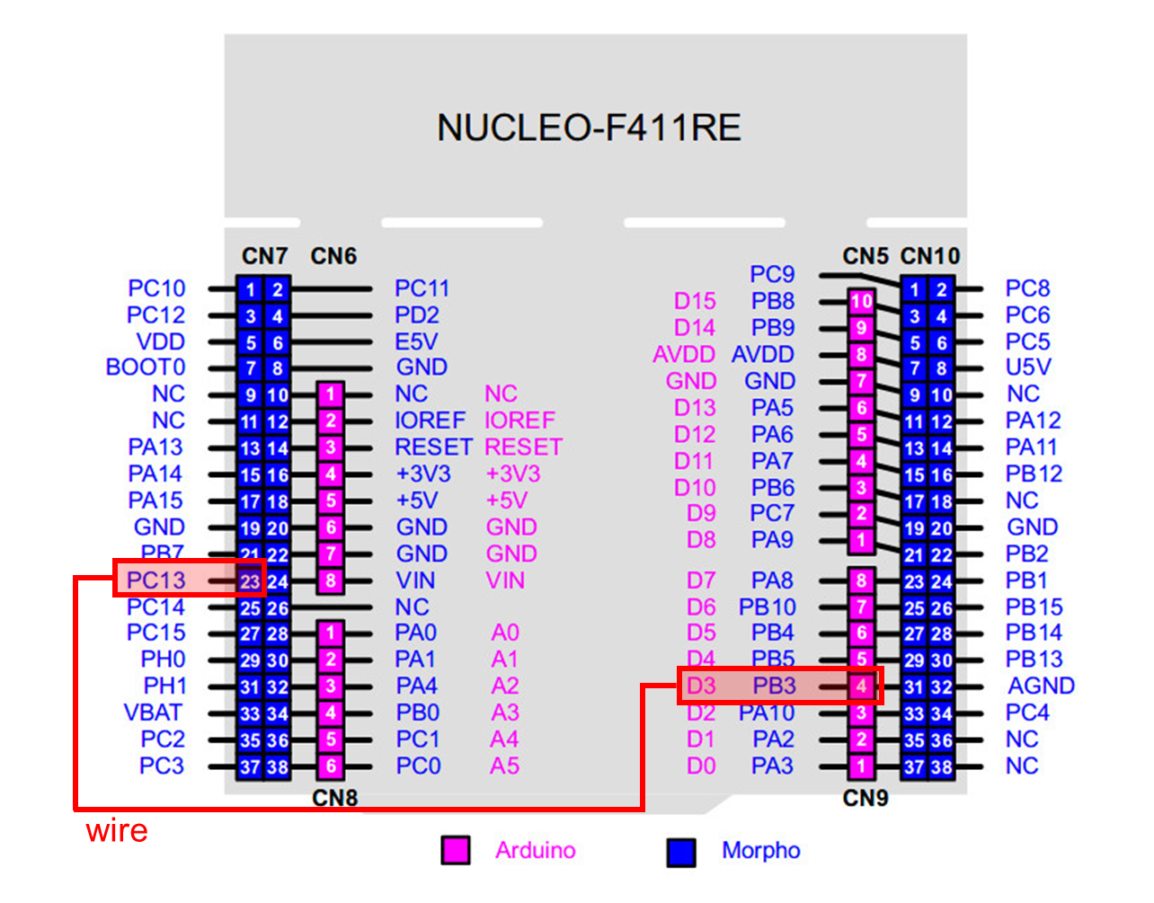
The user button pin is PC13, but this pin cannot be used in arduino. So, you should connect PC13 to pinName D3 by using wire.

  1. Click on upload button.

  2. Whenever the user button(BT1) is pressed (at fall), LED should be ON. When the button is released, the LED should be OFF.


Tutorial: STM32F4xx

1.Tutorial: Managing library header files

Read how to manage library header files for MCU register configurations. Apply it in your LAB.

2.Tutorial: Custom Initialization

Instead of writing initial setting functions for each registers, you can call a user defined function e.g. MCU_init() for the commonly used default initialization. Follow the tutorial and apply it in your LAB.


Problem 1: Counting numbers on 7-Segment using EXTI Button

1-1. Create HAL library

  1. Rename these files as ecEXTI2.h, ecEXTI2.c

    • You MUST write your name and other information at the top of the library code files.

    • Save these files in your directory EC \lib\.

  2. Declare and define the following functions in your library : ecEXTI2.h

ecEXTI.h

void EXTI_init(PinName_t pinName, int trig_type, int priority);
void EXTI_enable(uint32_t pin);  // mask in IMR
void EXTI_disable(uint32_t pin);  // unmask in IMR
uint32_t  is_pending_EXTI(uint32_t pin);
void clear_pending_EXTI(uint32_t pin);

1-2. Procedure

  1. Create a new project under the directory \EC\LAB\LAB_EXTI

  • The project name is “LAB_EXTI”.

  • Create a new source file named as “LAB_EXTI.c”

You MUST write your name on the source file inside the comment section.

2. Include your updated library in \EC\lib\ to your project.

  • ecGPIO2.h, ecGPIO2.c

  • ecRCC2.h, ecRCC2.c

  • ecEXTI2.h, ecEXTI2.c

  1. Use the decoder chip (74LS47). Connect it to the breadboard and 7-segment display.

    Then, you need only 4 Digital out pins of MCU to display from 0 to 9.

  2. First, check if every number, 0 to 9, can be displayed properly on the 7-segment.

  3. Then, create a code to display the number counting from 0 to 9 and repeating.

    • Count up only by pressing the push button (External Interrupt)

  4. You must use your library function of EXTI.

Configuration

Digital In for Button (B1)
Digital Out for 7-Segment decoder

Digital In

Digital Out

PC13

PA7, PB6, PC7, PA9

PULL-UP

Push-Pull, No PullUp-PullDown, Medium Speed

Circuit Diagram

You need to include the circuit diagram

Discussion

  1. We can use two different methods to detect an external signal: polling and interrupt. What are the advantages and disadvantages of each approach?

Answer discussion questions

  1. What would happen if the EXTI interrupt handler does not clear the interrupt pending flag? Check with your code

    Answer discussion questions

Code

Your code goes here.

Explain your source code with the necessary comments.

// YOUR MAIN CODE ONLY
// YOUR CODE

Results

Experiment images and results go here

Show experiment images /results

Problem 2: Counting numbers on 7-Segment using SysTick

Display the number 0 to 9 on the 7-segment LED at the rate of 1 sec. After displaying up to 9, then it should display ‘0’ and continue counting.

When the button is pressed, the number should be reset ‘0’ and start counting again.

2-1. Create HAL library

  1. Rename these files as ecSysTick2.h, ecSysTick2.c

    • You MUST write your name and other information at the top of the library code files.

    • Save these files in your directory EC \lib\.

  2. Declare and define the following functions in your library : ecSysTick2.h

ecSysTick.h

void SysTick_init(uint32_t msec);
void delay_ms(uint32_t msec);
uint32_t SysTick_val(void);
void SysTick_reset (void);
void SysTick_enable(void);
void SysTick_disable (void)

2-2. Procedure

  1. Create a new project under the directory

    \EC\LAB\LAB_EXTI_SysTick

  • The project name is “LAB_EXTI_SysTick”.

  • Create a new source file named as “LAB_EXTI_SysTick.c”

You MUST write your name on the source file inside the comment section.

2. Include your updated library in \EC\lib\ to your project.

  • ecGPIO2.h, ecGPIO2.c

  • ecRCC2.h, ecRCC2.c

  • ecEXTI2.h, ecEXTI2.c

  • ecSysTick2.h, ecSysTick2.c

  1. Use the decoder chip (74LS47). Connect it to the bread board and 7-segment display.

    Then, you need only 4 Digital out pins of MCU to display from 0 to 9.

  2. First, check if every number, 0 to 9, can be displayed properly on the 7-segment.

  3. Then, create a code to display the number counting from 0 to 9 and repeats at the rate of 1 second.

  4. When the button is pressed, it should start from '0' again.

    Use EXTI for this button reset.

Configuration

Digital In for Button (B1)
Digital Out for 7-Segment decoder

Digital In

Digital Out

PC13

PA7, PB6, PC7, PA9

PULL-UP

Push-Pull, No Pull-up-Pull-down, Medium Speed

Circuit Diagram

You need to include the circuit diagram

Code

Your code goes here.

Explain your source code with necessary comments.

// YOUR MAIN CODE ONLY
// YOUR CODE

Results

Experiment images and results

Show experiment images /results

Reference

Complete list of all references used (github, blog, paper, etc)

Troubleshooting

(Option) You can write a Troubleshooting section

PreviousLAB: GPIO Digital InOut 7-segmentNextLAB: Timer & PWM

Last updated 7 months ago

Was this helpful?

: ecEXTI2_student.h, ecEXTI2_student.c

Refer to an

image

Add

: ecSysTick_student.h, ecSysTick_student.c

image

Add

attachInterrupt()
Download sample header files
sample code
demo video link
Download sample header files
demo video link
Tutorial: arduino-stm32 Part1 | EC
Tutorial: Managing library header files | EC
Tutorial: Custom initialization | EC
Logo
Logo
Logo