Tutorial: 7-Segment Display
Using 7-Segment Display in STM32F4
Option 1. With 7-segment decoder
Option 2. Without using 7-segment decoder
Option 3. Without using 7-segment decoder on JKIT evaluation board
Circuit Description
Hardware Specification
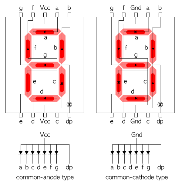
7-segment display (5101ASR)
BCD 7-segment decoder


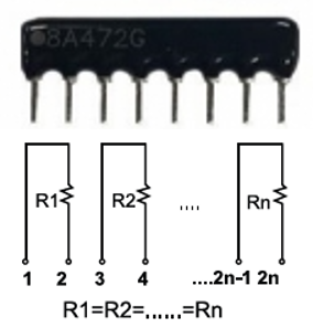
Array resistor (B331J)
Option 1. Connecting with a BCD 7-segment decoder

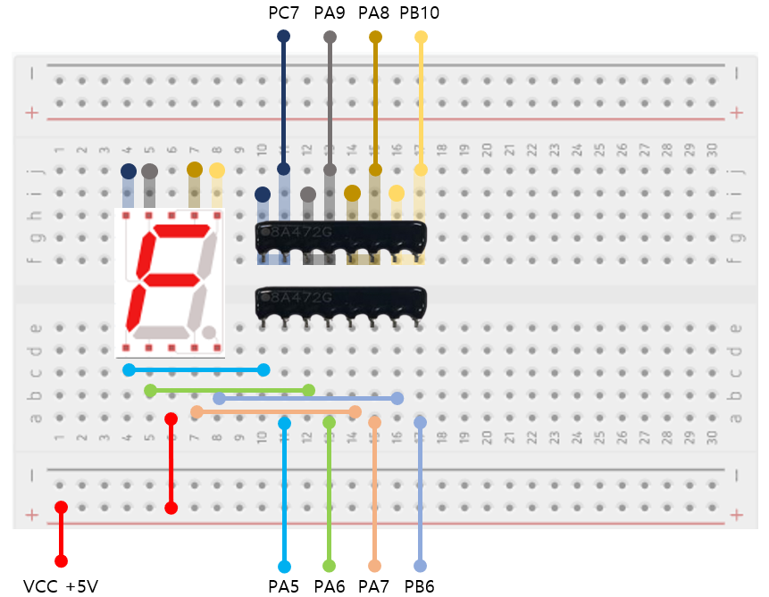
Option 2. Connecting without a 7-segment decoder
Circuit Configuration
Example Code
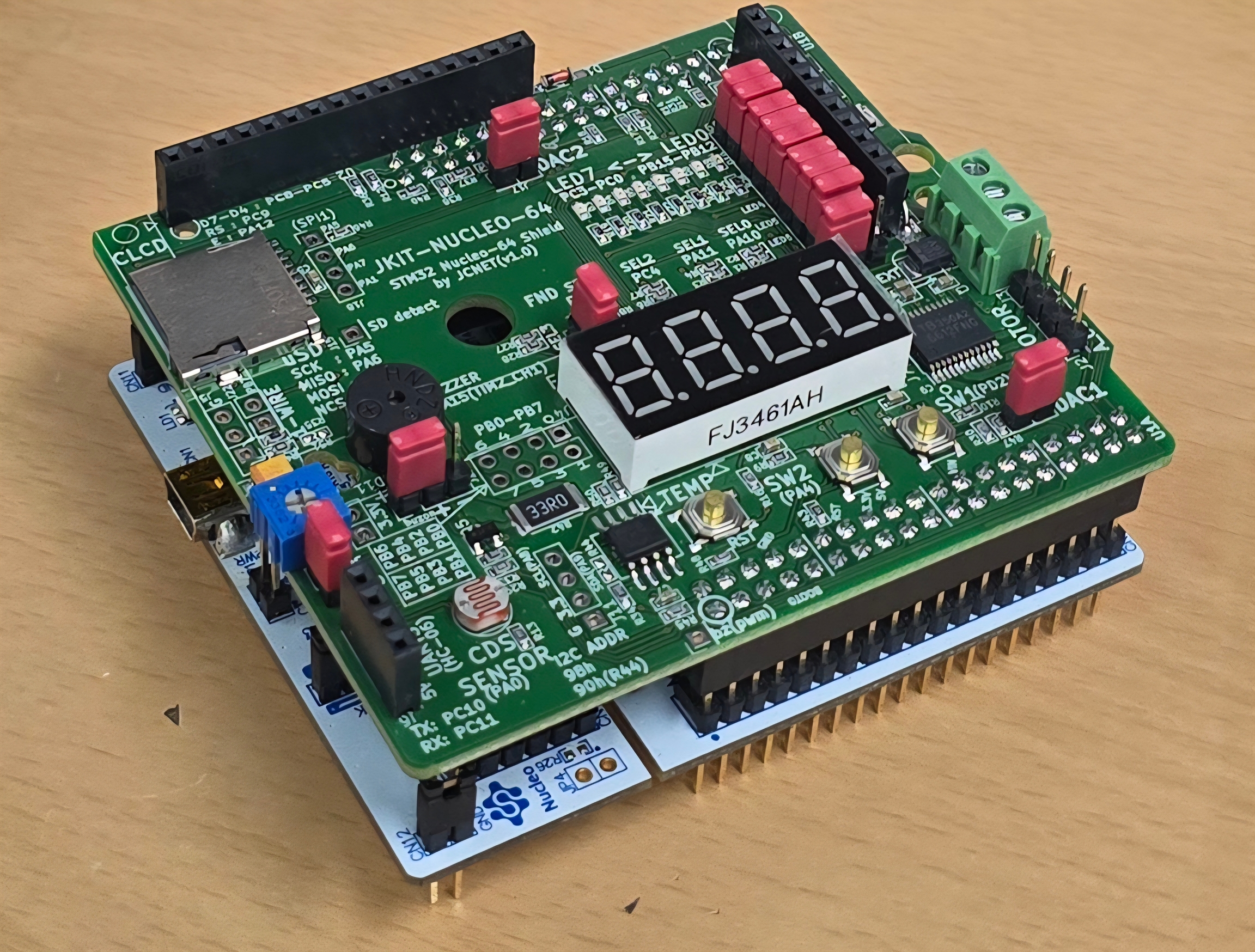
Option 3. Without using a 7-segment decoder on JKIT evaluation board
Circuit Configuration
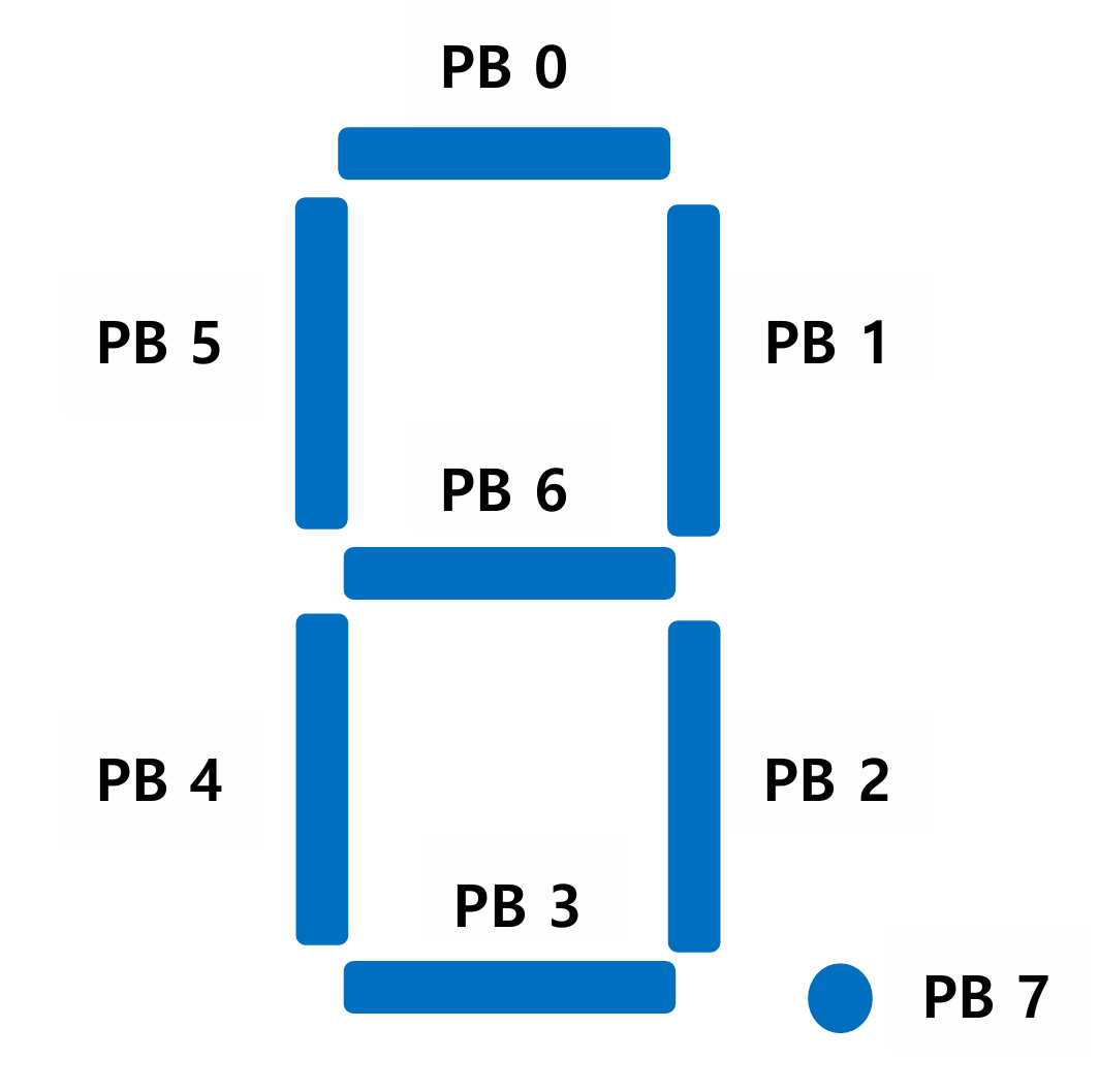
1. Digital Out: 7-Segment display number
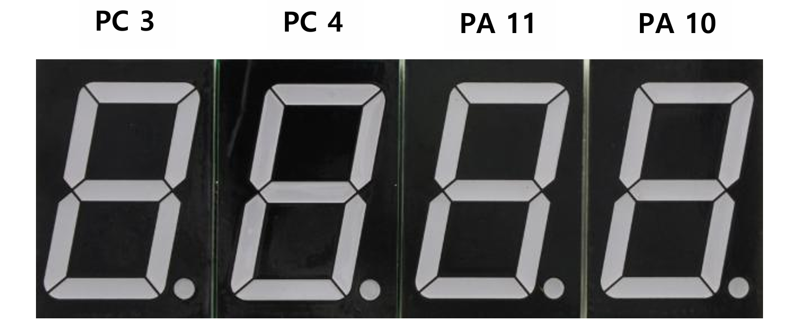
2. Digital Out: Select 7-Segment display
Example Code
Exercise
Last updated