💾
EC
  • Introduction
  • EC Course
    • Syllabus
    • Preparation for EC
    • Tutorial
      • Tutorial: arduino-stm32
        • Tutorial: arduino-stm32 Installation
        • Tutorial: arduino-stm32 Part1
        • Tutorial: arduino-stm32 Part2
      • Tutorial: MDK uVision
        • Tutorial: Installing MDK uVision
        • Tutorial: Create a Project with uVision
        • Tutorial: Adding library header in uVision
        • Tutorial: Re-using Project Configuration
        • Debugging in uVision
      • Tutorial: PlatformIO in CLion
      • Tutorial: PlatformIO in VSCode
      • Tutorial: Repository Management
      • Tutorial: Managing library header files
      • Tutorial: PinName Configuration
      • Tutorial: Bitwise Macro
      • Tutorial: Custom initialization
      • Tutorial: Documentation
      • Tutorial: Creating Application API
      • Tutorial: 7-Segment Display
      • Tutorial: DC motor driver connection
      • Tutorial: USART with TeraTerm
      • Tutorial: Finite State Machine programming
      • Tutorial: Bluetooth
      • Tutorial: Zigbee with Nucleo board
    • LAB
      • LAB Report Template
      • LAB: Smart mini-fan with STM32-duino
      • LAB: Portable Fan with mbed
      • LAB: GPIO Digital InOut
      • LAB: GPIO Digital InOut 7-segment
      • LAB: EXTI & SysTick
      • LAB: Timer & PWM
      • LAB: Stepper Motor
      • LAB: Input Capture - Ultrasonic
      • LAB: USART - LED, Bluetooth
      • LAB: ADC - IR reflective sensor
      • LAB: Line Tracing RC Car
    • Sample code
      • Code Templates
    • Hardware
      • Nucleo-F411RE
      • LAB Hardware
        • Electronic Chips
        • HUINS Embedded Kit
    • Projects
      • Line Tracing Car Project
      • Design Project
        • Past Projects
      • Project Grading Criteria
    • Study Resource for MCU
      • Hexa-Decimal Table
      • Bitwise Op for Register
      • System Clock
      • Timer
      • USART
      • ADC
  • STM32 M4 Programming
    • Documentation
      • C++ API Docs
    • Firmware Library
      • PinName Configuration
      • GPIO Digital
      • RCC
      • EXTI_SysTick
      • TIMER
      • USART
    • Troubleshooting
    • mbed for STM32
      • Tutorial: mbed-Part 1
      • Tutorial: mbed - Part 2
      • Tutorial: mbed - Part 3
      • Using mbed API on uVision
    • mbed OS
  • Other Programming
    • Arduino
    • Socket Programming
      • Window Socket Programming
      • Arduino WiFi
    • Cube-MX
    • Github
    • Markdown
      • Example: API documentation
    • MATLAB
  • C Programming
    • C-Programming Lessons
      • Installing Visual Studio Community
        • Visual Studio Community 2022
      • Installing VS Code(Mac/Linux)
      • Creating Header Lib
      • Pointer
      • Array
      • 2D Array
      • Structure
      • Dynamic Alloc
      • Bitwise Operation
  • Numerical Programming
    • Syllabus
    • Preparation for NP
    • Math Review
    • Tutorial
      • TA Session Video
      • Tutorial: NP Library Header Files
      • Tutorial - Sine Taylor
      • Tutorial: Passing a Function, Function callback
      • Tutorial: Nonlinear solver
      • Tutorial: Differentiation
      • Tutorial: Integration
      • Tutorial: Matrix Structure
      • Tutorial: Eigenvalue problem
      • Tutorial: ODE-IVP
      • Tutorial: Curve Fitting
      • Tutorial: Create Github Repos of NP lib
      • Tutorial: Version Control in Github
      • Tutorial: Documentation with Markdown
      • Exercise: Version Control and Documentation
    • Example: MATLAB
    • Example: NP Library
    • Assignment
      • Assignment Factorial and Power
      • Assignment: Version Control and Documentation
    • Problem Bank
Powered by GitBook
On this page
  • Introduction
  • Requirement
  • Problem 0: STM-Arduino
  • Procedure
  • Problem 1: EC library
  • Using HAL library
  • Example Code
  • Problem 2: Measurement from multiple analog sensors
  • IR Reflective Sensors (TCRT 5000)
  • Procedure
  • Configuration
  • Line Tracing
  • Circuit Diagram
  • Discussion
  • Code
  • Results
  • Reference
  • Troubleshooting

Was this helpful?

  1. EC Course
  2. LAB

LAB: ADC - IR reflective sensor

Date: 2023-11-13

Author/Partner:

Github: repository link

Demo Video: Youtube link

PDF version:

Introduction

Create a simple program that uses ADCs to use analog sensors. For this lab, we will use two IR reflective sensors.

The ADCs are triggered by a timer at the given sampling rate.

This lab will be extended to Project: Line Tracing Car

You must submit

  • LAB Report (*.md & *.pdf)

  • Zip source files(main*.c, ecRCC.h, ecGPIO.h, ecSysTick.c etc...).

    • Only the source files. Do not submit project files

Requirement

Hardware

  • MCU

    • NUCLEO-F411RE

  • Actuator/Sensor/Others:

    • IR Reflective Sensor (TCRT 5000) x2

Software

  • Keil uVision, CMSIS, EC_HAL library

Problem 0: STM-Arduino

Procedure

  1. Create a new project under the directory\repos\EC\LAB\LAB_ADC

Problem 1: EC library

Using HAL library

Download

Change the file names as

  • ecADC2.c

  • ecADC2.h

ecADC2.h

/////////////////////////////////////////////////////
// ADC default setting
/////////////////////////////////////////////////////

// ADC init
// Default:  one-channel mode, continuous conversion
// Default: HW trigger - TIM3 counter, 1msec
void ADC_init(PinName_t pinName);
void JADC_init(PinName_t pinName);


// Multi-Channel Scan Sequence 
void ADC_sequence(PinName_t *seqCHn, int seqCHnums); 
void JADC_sequence(PinName_t *seqCHn, int seqCHnums); 

// ADC start
void ADC_start(void);

// flag for ADC interrupt
uint32_t is_ADC_EOC(void);
uint32_t is_ADC_OVR(void);
void clear_ADC_OVR(void);

// read ADC value
uint32_t ADC_read(void);


/////////////////////////////////////////////////////
// Advanced Setting
/////////////////////////////////////////////////////
// Conversion mode change: CONT, SINGLE / Operate both ADC,JADC
void ADC_conversion(int convMode); 					
void ADC_trigger(TIM_TypeDef* TIMx, int msec, int edge);

// Private Function
void ADC_pinmap(PinName_t pinName, uint32_t *chN);

Fill-In missing code in ecADC2_student.c

You must update your header files in the directory EC\include\. and add in ecSTM32F4v2.h

void ADC_init(PinName_t pinName){
// ...
// ...
	// 2. Regular / Injection Group 
	//Regular: SQRx, Injection: JSQx

	// 3. Repetition: Single scan or Continuous scan conversion
	ADC1->CR2 |= ___________;      			// default : Continuous conversion mode	
	
	// 4. Single(one) Channel or Scan(multi-channel) mode  
	// Configure the sequence length		// default: one-channel length
	ADC1->SQR1 &= ___________; 				// 0000: one channel length in the regular channel conversion sequence
	
	// Configure the multiple channel sampling sequence 
	ADC1->SQR3 &= ~ADC_SQR3_SQ1;			// SQ1 clear 
	ADC1->SQR3 |= ___________; 				// Choose the first channelID to sample
	
	// Default:  Single(one-channel) Channel mode 
	ADC1->CR1 &= ___________;				// 0: One-channel mode 		
	
	// 5. Interrupt Enable
	// Enable EOC(conversion) interrupt. 
	ADC1->CR1 &= ~ADC_CR1_EOCIE;          	// Interrupt reset
	ADC1->CR1 |= ___________;           	// Interrupt enable
	
// ...
// ...
}
void JADC_init(PinName_t pinName){
// ...
// ...
	// 2. Injection Group 
	//    Injection: JSQx

	// 3. Repetition: Single or Continuous conversion
	ADC1->CR2 |= _____________;     		// Enable Continuous conversion mode	
	
	// 4. Single Channel or Scan mode
	//  - Single Channel: scan mode, right alignment	
	ADC1->CR1 |= _____________;			// 1: Scan mode enable 
	ADC1->CR2 &= _____________;   			// 0: Right alignment	

	// Configure the injected channel sequence length
	ADC1->JSQR &= _____________; 			// 00: conversion in the inject channel

	// Configure the injected channel sequence 
	ADC1->JSQR &= ~ADC_JSQR_JSQ1;			// SQ1 clear bits
	ADC1->JSQR |= _____________; 			// Choose the channel to convert firstly

	// 5. Interrupt Enable
	// Enable JEOC(conversion) interrupt.
	ADC1->CR1 &= ~ADC_CR1_JEOCIE;   		// JEOC interrupt reset
	ADC1->CR1 |= _____________;			// JEOC interrupt enable
		
// ...
// ...
}

Example Code

Check your library files by running the following examples.

Example 1: One Analog sensor (ADC)

  • Single-Channel, Continuous Scan

  • 1msec ADC triggering with TIM3

#include "ecSTM32F4v2.h"
// #include "ecADC.h"


//IR parameter//
uint32_t value;

void setup(void);
	
int main(void) { 
	
	// Initialiization --------------------------------------------------------
	setup();
	
	// Inifinite Loop ----------------------------------------------------------
	while(1){
		printf("value = %d \r\n",value);
		printf("\r\n");
		delay_ms(1000);
	}
}

// Initialiization 
void setup(void)
{	
	RCC_PLL_init();		// System Clock = 84MHz
	UART2_init();		// UART2 Init
	SysTick_init();		// SysTick Init
	ADC_init(PB_0);		// Default: HW triggered by TIM3 counter @ 1msec
}

// ADC Interrupt
void ADC_IRQHandler(void){
    if(is_ADC_OVR())
		clear_ADC_OVR();

	if(is_ADC_EOC())
		value = ADC_read();
}

Example 2: Multiple Analog sensors (JADC)

  • Multi-Channel(2 channels), Continuous Scan

  • 1msec ADC triggering with TIM3

  • (ADC) Channel Sequence: SQ1=ADC_CH_8(PB_0) to SQ2=ADC_CH_9(PB_1)

  • (JADC): Channel Sequence: JSQ1=ADC_CH_8(PB_0)(PB_0) to JSQ1=ADC_CH_9(PB_1)

Use JADC instead of ADC for multiple-channel ADC

JADC: Has its own data register for each ADC channels

#include "ecSTM32F4v2.h"
// #include "ecADC.h"

//IR parameter//
uint32_t value1, value2;
PinName_t seqCHn[2] = {PB_0, PB_1};

void setup(void);

int main(void) { 
	// Initialiization --------------------------------------------------------
	setup();
	
	// Inifinite Loop ----------------------------------------------------------
	while(1){
		printf("value1 = %d \r\n",value1);
		printf("value2 = %d \r\n",value2);
		printf("\r\n");
		
		delay_ms(1000);
	}
}

// Initialiization 
void setup(void)
{	
	RCC_PLL_init();                 // System Clock = 84MHz
	UART2_init();			// UART2 Init
	SysTick_init();			// SysTick Init
	
	// ADC Init  Default: HW triggered by TIM3 counter @ 1msec
	JADC_init(PB_0);
	JADC_init(PB_1);

	// ADC channel sequence setting
	JADC_sequence(seqCHn, 2);
}


void ADC_IRQHandler(void){
	if(is_ADC_OVR())
		clear_ADC_OVR();
	
	if(is_ADC_JEOC()){		// after finishing sequence
		value1 = JADC_read(1);
		value2 = JADC_read(2);
	}
}

ADC: Shares the same data register from multiple channels

#include "ecSTM32F4v2.h"
// #include "ecADC.h"

//IR parameter//
uint32_t value1, value2;
int flag = 0;
PinName_t seqCHn[2] = {PB_0, PB_1};

void setup(void);

int main(void) { 
	// Initialiization --------------------------------------------------------
	setup();
	
	// Inifinite Loop ----------------------------------------------------------
	while(1){
		printf("value1 = %d \r\n",value1);
		printf("value2 = %d \r\n",value2);
		printf("\r\n");
		
		delay_ms(1000);
	}
}

// Initialiization 
void setup(void)
{	
	RCC_PLL_init();                         // System Clock = 84MHz
	UART2_init();				// UART2 Init
	SysTick_init();				// SysTick Init
	
	// ADC Init  Default: HW triggered by TIM3 counter @ 1msec
	ADC_init(PB_0);
	ADC_init(PB_1);

	// ADC channel sequence setting
	ADC_sequence(seqCHn, 2);
}


void ADC_IRQHandler(void){
	if(is_ADC_OVR())
		clear_ADC_OVR();
	
	if(is_ADC_EOC()){		// after finishing sequence
		if (flag==0)
			value1 = ADC_read();  
		else if (flag==1)
			value2 = ADC_read();
			
		flag =! flag;		// flag toggle
	}
}

Problem 2: Measurement from multiple analog sensors

IR Reflective Sensors (TCRT 5000)

TCRT5000 and TCRT5000L are reflective sensors that include an infrared emitter and phototransistor in a leaded package which blocks visible light.

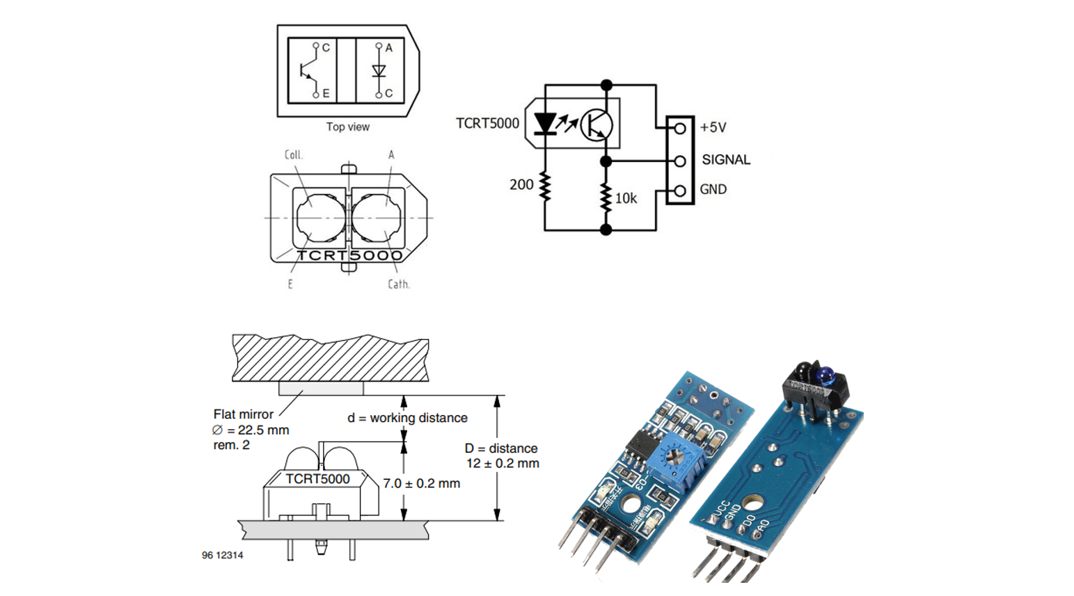
The HC-SR04 Ultrasonic Range Sensor Features:

  • Input Voltage : 5V

  • Detector type: phototransistor

  • Operating range within > 20 % relative collector current: 0.2 mm to 15 mm

  • Emitter wavelength: 950 nm

APPLICATIONS

  • Position sensor for shaft encoder

  • Detection of reflective material such as paper, IBM cards, magnetic tapes etc.

  • Limit switch for mechanical motions in VCR

Procedure

  1. Create a new project under the directory \repos\EC\LAB\LAB_ADC

  • The project name is “LAB_ADC_IR”

  • Create a new source file named as “LAB_ADC_IR.c”

You MUST write your name on the source file inside the comment section.

2. Update and use ecSTM32F411.h. This header should be defined as explained in

Configuration

Type
Port - Pin
Configuration

System Clock

PLL 84MHz

GPIO

PB_0 PB_1

Analog Mode No Pull-up Pull-down

ADC (JADC)

PB_0: ADC1_CH8 (1st channel) PB_1: ADC1_CH9 (2nd channel)

ADC Clock Prescaler /8 12-bit resolution, right alignment Continuous Conversion mode Scan mode: Two channels in regular group External Trigger (Timer3 Trigger) @ 1kHz Trigger Detection on Rising Edge

TIM3

Up-Counter, Counter CLK 1kHz OC1M(Output Compare 1 Mode) : PWM mode 1 Master Mode Selection: (Trigger) OC1REF

Line Tracing

  • Create a logic to trace a dark line on white background surface for your RC car.

  • Use 2 IR reflective sensors to detect if the black line is in between the sensors. It should display whether the system needs to move Left or Right to keep the line between sensors.

  • Set the ADC sampling rate trigger to be 1KHz

  • Determine the threshold value to differentiate dark and white surface of the object.

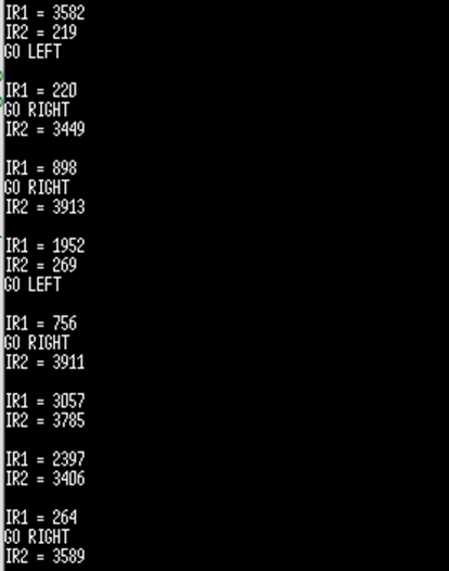
  • Display (1) and (2) on serial monitor of Tera-Term. Print the values every second.

    ​ (1) reflection value of IR1 and IR2

    ​ (2) print ‘GO LEFT’ or ‘GO ‘RIGHT’

Display Example

Circuit Diagram

You need to include the circuit diagram

Discussion

  1. How would you change the code if you need to use 3 Analog sensors?

Answer discussion questions

  1. Which registers should be modified if you need to use Injection Groups instead of regular groups for 2 analog sensors?

    Answer discussion questions

Code

Explain your source code with necessary comments.

// YOUR MAIN CODE ONLY
// YOUR CODE

Results

Experiment images and results

Show experiment images /results

Reference

Complete list of all references used (github, blog, paper, etc)

Troubleshooting

(Option) You can write Troubleshooting section

PreviousLAB: USART - LED, BluetoothNextLAB: Line Tracing RC Car

Last updated 6 months ago

Was this helpful?

Follow the tutorial:

First, download and read IR Reflective Sensor(TCRT 5000):

image
line
image
image

Your code goes here:

Add

ADC with photodector and sound sensor
ecADC2_student.c
ecADC2_student.h
Spec Sheet
ADD Code LINK such as github
demo video link
Tutorial: arduino-stm32 Part2 | EC
Logo