LAB: GPIO Digital InOut
LAB: GPIO Digital InOut
Date: 2024-09-1
Author/Partner:
Github: repository link
Demo Video: Youtube link
PDF version:
Introduction
In this lab, you are required to create a simple program that toggle multiple LEDs with a push-button input. Create HAL drivers for GPIO digital in and out control and use your library.
You must submit
LAB Report (*.pdf)
Zip source files(main*.c, ecRCC.h, ecGPIO.h etc...).
Only the source files. Do not submit project files
Requirement
Hardware
MCU
NUCLEO-F411RE
Actuator/Sensor/Others:
LEDs x 3
Resistor 330 ohm x 3, breadboard
Software
Keil uVision, CMSIS, EC_HAL library
Problem 0: STM-Arduino
We are going to create a simple program that turns LED(LD2) on and off by pressing the user button(BT1), using Arduino Syntax
GPIO Digital In/Out
Create a new project under the directory \repos\EC\lab\
The project folder name is “\LAB_GPIO_DIO_LED”.
Configures the specified pin to behave either as an input or an output.
pin: the pin number to set the model of.
mode: INPUT, OUTPUT or INPUT_PULLUP.
Look up for pinMode() function in arduino reference for detail description.
Example code
Open Arduino IDE and Create a new program named as ‘TU_arduino_GPIO_LED_button.ino’.
Write the following source code: source code.
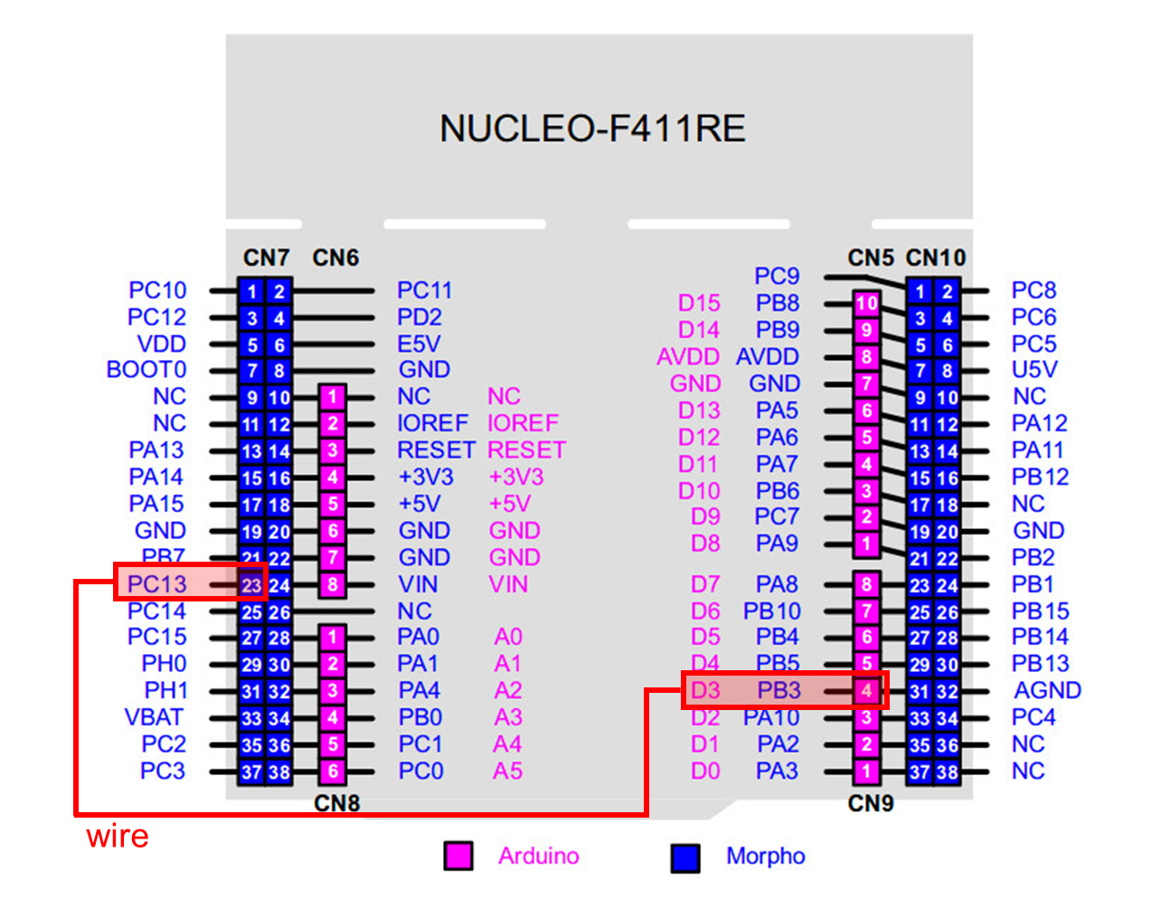
The user button pin is PC13, but this pin cannot be used in arduino. So, you should connect PC13 to pinName D3 by using wire.
Click on upload button. Push the reset button(black) and check the performance.
The LED(LD2) should be turned on when the button is pressed.
Problem 1: Create EC_HAL library
Procedure
Create the library directory \repos\EC\include\.
Save your header library files in this directory. See here for detail.
DO NOT make duplicates of library files under each project folders
Create your own library for Digital_In and Out : ecGPIO2.h, ecGPIO2.c
Use the provided
ecRCC2.handecRCC2.cModify
ecGPIO2.c,ecGPIO2.h
ecRCC2.h (provided)
ecGPIO2.h
Example code in ecGPIO2.c
Problem 2: Toggle a single LED with Button
Procedure
Create a new project under the directory
\repos\EC\lab\
The project name is “LAB_GPIO_DIO_LED”.
Name the source file as “LAB_GPIO_DIO_LED.c”
Use the example code provided here.
2. Include your library ecGPIO2.h, ecGPIO2.c in \repos\EC\include\.
You MUST write your name in the top of the source file, inside the comment section.
3. Toggle the LED by pushing the button.
Push button (LED ON), Push Button (LED OFF) and repeat
Configuration
Digital In
Digital Out
GPIOC, Pin 13
GPIOA, Pin 5
PULL-UP
Open-Drain, Pull-up, Medium Speed
Code
Your code goes here:
Explain your source code with necessary comments.
Sample Code
Discussion
Find out a typical solution for software debouncing and hardware debouncing.
What method of debouncing did this NUCLEO board use for the push-button(B1)?
Problem 3: Toggle multiple LEDs with button
Procedure
Create a new project under the directory
\repos\EC\lab\
The project name is “LAB_GPIO_DIO_multiLED”.
Name the source file as “LAB_GPIO_DIO_multiLED.c”
You MUST write your name in the top of the source file, inside the comment section.
Include your library ecGPIO2.h, ecGPIO2.c in
\repos\include\.Connect 4 LEDs externally with necessary load resistors.
As Button B1 is Pressed, light one LED at a time, in sequence.
Example: LED0--> LED1--> …LED3--> …LED0….
Configuration
Digital In
Digital Out
GPIOC, Pin 13
PA5, PA6, PA7, PB6
PULL-UP
Push-Pull, Pull-up, Medium Speed
Circuit Diagram
Circuit diagram
You need to modify the circuit diagram

Code
Your code goes here
Explain your source code with necessary comments.
Results
Experiment images and results
Show experiment images /results
Add demo video link
Problem 4: Toggle LED with Digital Sensor( )
Procedure
Create a new project under the directory
\repos\EC\lab\
The project name is “LAB_GPIO_DIO_multiLED”.
Name the source file as “LAB_GPIO_DIO_multiLED.c”
You MUST write your name in the top of the source file, inside the comment section.
Include your library ecGPIO2.h, ecGPIO2.c in
\repos\include\.Connect 4 LEDs externally with necessary load resistors.
As Button B1 is Pressed, light one LED at a time, in sequence.
Example: LED0--> LED1--> …LED3--> …LED0….
Configuration
Digital In
Digital Out
GPIOC, Pin 13
PA5, PA6, PA7, PB6
PULL-UP
Push-Pull, Pull-up, Medium Speed
Circuit Diagram
Circuit diagram
You need to modify the circuit diagram
Code
Your code goes here
Explain your source code with necessary comments.
Results
Experiment images and results
Show experiment images /results
Add demo video link
Discussion
Find out a typical solution for software debouncing and hardware debouncing. What method of debouncing did this NUCLEO board use for the push-button(B1)?
Answer discussion questions
Reference
Complete list of all references used (github, blog, paper, etc)
Troubleshooting
(Option) You can write a Troubleshooting section
Last updated